Rotary compressor of centralized air-breathing and exhaust

A rotary compressor and suction pipe technology, applied in the field of refrigeration compressors, can solve the problems of increasing the fluid noise of the compressor, and achieve the effects of eliminating vibration and noise, improving airflow characteristics, and smooth and continuous suction

Inactive Publication Date: 2007-12-05
李玉斌
View PDF4 Cites 0 Cited by
  • Summary
  • Abstract
  • Description
  • Claims
  • Application Information

AI Technical Summary

Problems solved by technology

In addition, the exhaust of the cylinder is axial exhaust, and the airflow pulse caused by intermittent exhaust and axial exhaust increases the fluid noise of the compressor

Method used


Image

  • Rotary compressor of centralized air-breathing and exhaust
  • Rotary compressor of centralized air-breathing and exhaust
  • Rotary compressor of centralized air-breathing and exhaust

Examples


Embodiment 2

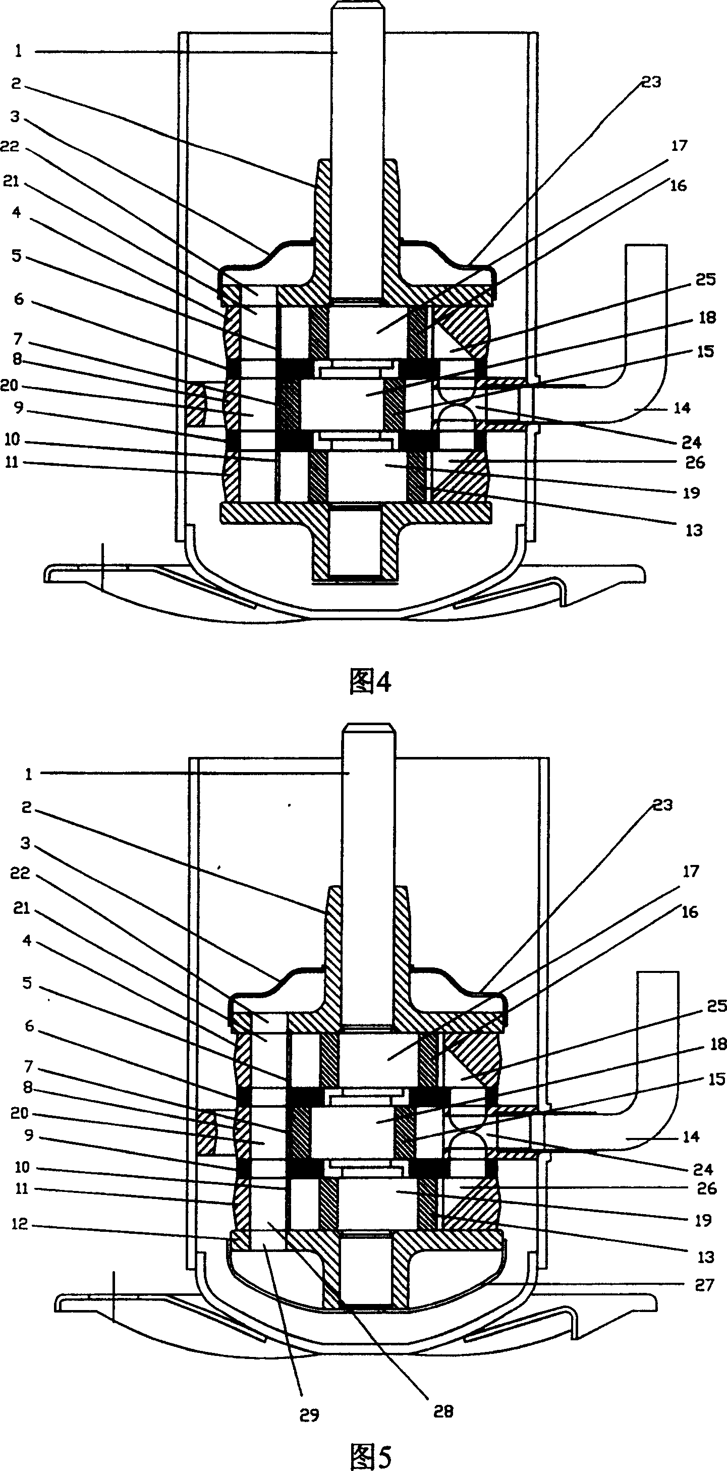
[0036] Figure 5 and Figure 6 show the second embodiment of the present invention, which is different from the first embodiment: the cylinder head 12 is also provided with a lower exhaust muffler 27, and the lower end of the exhaust passage 20 corresponds to the cylinder head 12 respectively. A lower exhaust port 28 and a cylinder head through hole 29 are provided, and the exhaust channel 20 communicates with the lower exhaust muffler 27 through the lower exhaust port 28 and the cylinder head through hole 29 . At this time, part of the gas discharged from the cylinder can enter the lower exhaust muffler 27 through the lower exhaust port 28 of the exhaust passage and the through hole 29 of the cylinder head, so that the airflow can be buffered and helps to reduce the airflow pulse.

Embodiment 3

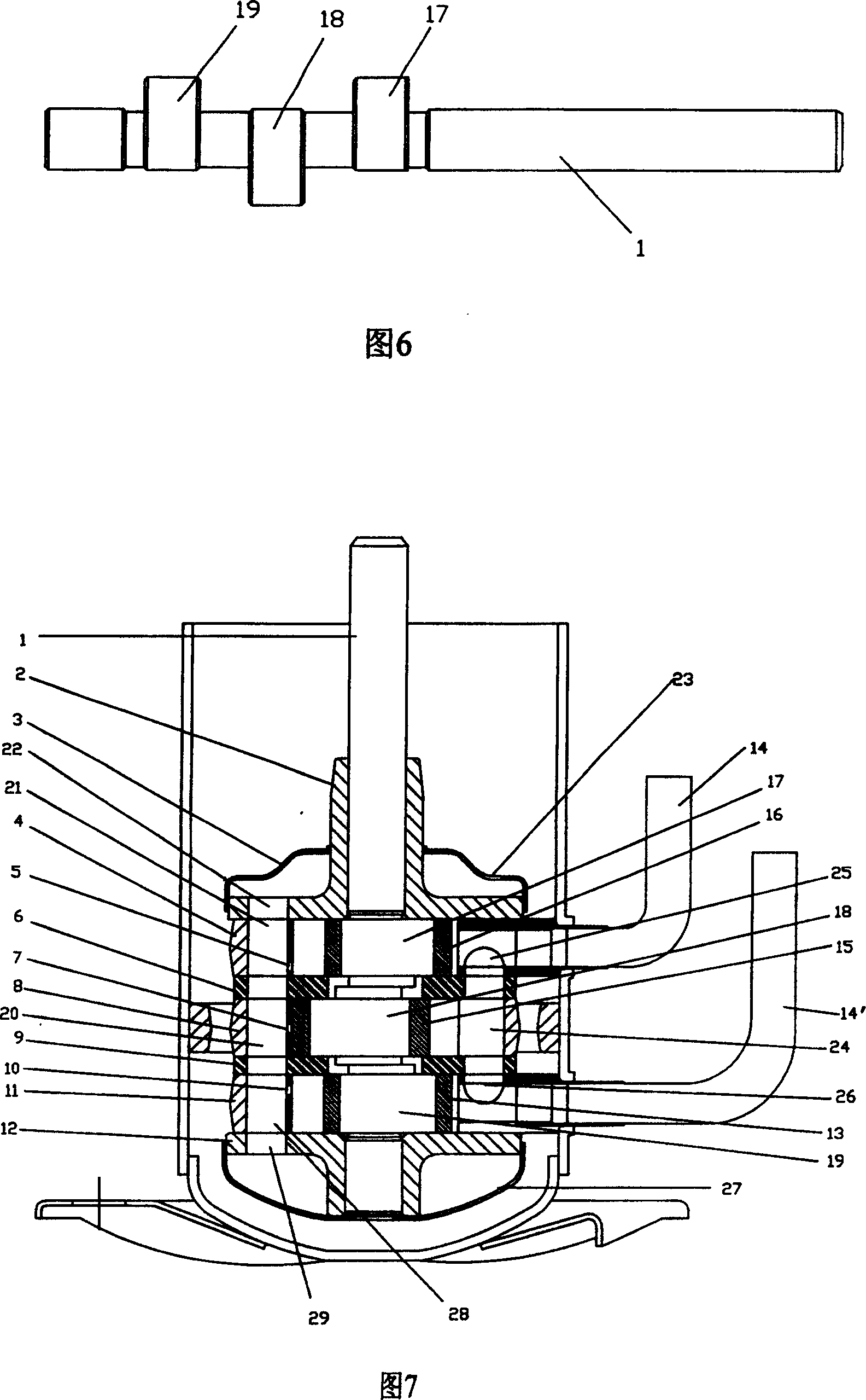
[0038] Fig. 7 describes the third embodiment of the present invention, which is different from the second embodiment: there are two suction pipes 14 and 14', which communicate with the suction holes 25, 26 of the upper cylinder 4 and the lower cylinder 11 respectively.

Embodiment 4

[0040] Figure 8 shows the fourth embodiment of the present invention, which is different from the second embodiment: a cylinder 30 is added below the lower cylinder 11, and a corresponding piston 34 and crank throw 35 are added, so that the compressor has four cylinders in total. The spatial phase difference of the four bell cranks is 90°. The upper part of its cylinder wall of the cylinder 30 is provided with an exhaust hole 31 communicating with the exhaust passage 20, and the air intake side is provided with an air intake channel 32 communicated with the air intake channels of other cylinders. Two suction pipes 14 and 14' are arranged to communicate with the suction holes 24, 26 of the two cylinders 8, 11 in the middle respectively.


PUM


Abstract

The present invention discloses a rotary compressor of centralized air-breathing and exhaust which includes shell, machine core, air suction pipe, motor stator, rotor and reservoir. The cylinder inner the machine core is three or more and sets with same axis, the number and position of the piston as well as crank is corresponding to the cylinder, and the phase difference of two adjacent cranks is equal; the exhaust hole of each cylinder lies in the same side of the cylinder and on the wall of the cylinder, the lateral cylinder body nearby the cylinder exhaust hole has a exhaust channel which connects to the exhaust hole of each cylinder; the number of the air suction pipes is less than the number of the cylinders, the cylinders have air suction channel which connect with each other, the air suction pipe connects to the air suction channel of the cylinder. This invention can implement centralized air-breathing and exhaust, which improves the air stream characteristics of air suction side and exhaust side as well as dynamical characteristics, and also it is suitable for the gas compression refrigeration of the device such as air-condition.

Description

technical field [0001] The invention relates to a refrigeration compressor, in particular to a rotary compressor with centralized suction and centralized exhaust. Background technique [0002] The scientific name of rotary compressor is rolling piston compressor, also known as rolling rotor compressor and rotary compressor. Its basic design is the single-cylinder structure shown in Figure 1, that is, one cylinder is used to complete the work of suction→compression→exhaust. When the compressor is applied in the frequency conversion condition and high power range, the vibration and noise problems of the traditional single-cylinder compressor are very prominent, and the efficiency is also reduced. [0003] For this reason, a compressor with a double-cylinder structure came into being. As shown in Figure 2, it is provided with two cylinders of the same specification in the coaxial direction. The phase difference between the two crank throws on the crankshaft is 180°. The two cy...

Claims


Application Information

Patent Timeline
Patent Type & Authority Patents(China)
IPC IPC(8): F04C29/06
Inventor 李玉斌
Owner 李玉斌
Why Eureka
Try Eureka