Pipe cutter

a cutter and pipe technology, applied in the field of pipe cutters, can solve the problems of superfluous post-processing of cut edges, time-consuming and labor-intensive, etc., and achieve the effect of improving the cut quality

Inactive Publication Date: 2011-10-11
CEKA ELEKTROWERKZEUGE
View PDF16 Cites 19 Cited by
  • Summary
  • Abstract
  • Description
  • Claims
  • Application Information

AI Technical Summary

Benefits of technology

[0008]It is the object of the present invention to provide a pipe cutter having improved cut quality.
[0011]According to the invention, the tool inner head has at least one spring-mounted cutting wheel head comprising a cutting wheel, the cutting wheel head being spring-mounted in the inner head part and the cutting wheel being mounted so as to be rotatable about the cutting wheel axis in the cutting wheel head. As a result of the spring mounting, it is possible to exert a defined feed force on the pipe. Thus, a defined pretensioning force which decreases with increasing cutting depth and thus permits gentle cutting without drawing-in of the pipe and without burr formation can be set by means of the springs. In addition, the pipe is supported in the pipe holder—formed by the inner jaws—in such a way—either by a plurality of appropriately arranged spring-loaded cutting wheels or by cutting wheel / wheels and support roller / rollers—that a right-angled orientation of the pipe relative to the cutting wheel is achieved and is ensured. In particular, the pipe can be clamped in the tool head and can be encompassed there in such a way that it is automatically oriented at right angles in the head. The parting at right angles to the pipe axis is decisive for the quality of the cut. With the development, according to the invention, of the pipe cutting device parting with a clean cut, straight cut and burr-free edges is achievable. Consequently, time-consuming post-processing of the cut edges is superfluous. Furthermore, contraction of the pipe toward the inside of the pipe is also prevented by the defined delivery of force during parting.
[0013]In addition, support roller / rollers and cutting wheel / wheels are preferably coated. By coating the support rollers / bearings, firstly the life of the rollers can be increased and secondly it is possible to choose a friction reducing coating (antifriction or nonstick coating), with the result that the force required during cutting can be reduced. Since many tools operate fairly close to the limit in terms of force in the case of large pipe diameters, a reduced applied force for cutting the pipe is a major advantage.

Problems solved by technology

Consequently, time-consuming post-processing of the cut edges is superfluous.

Method used


Image

  • Pipe cutter
  • Pipe cutter
  • Pipe cutter

Examples


Embodiment Construction

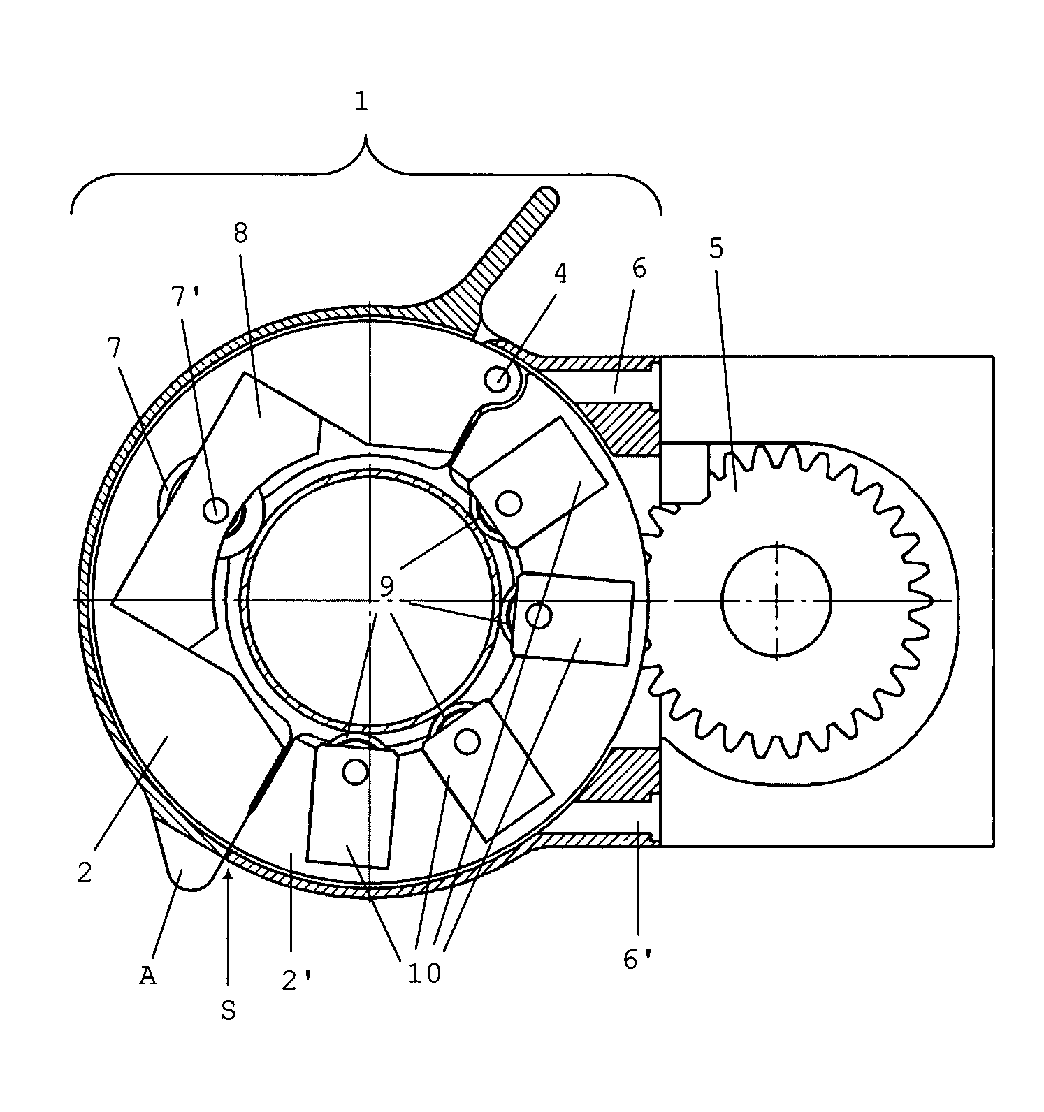
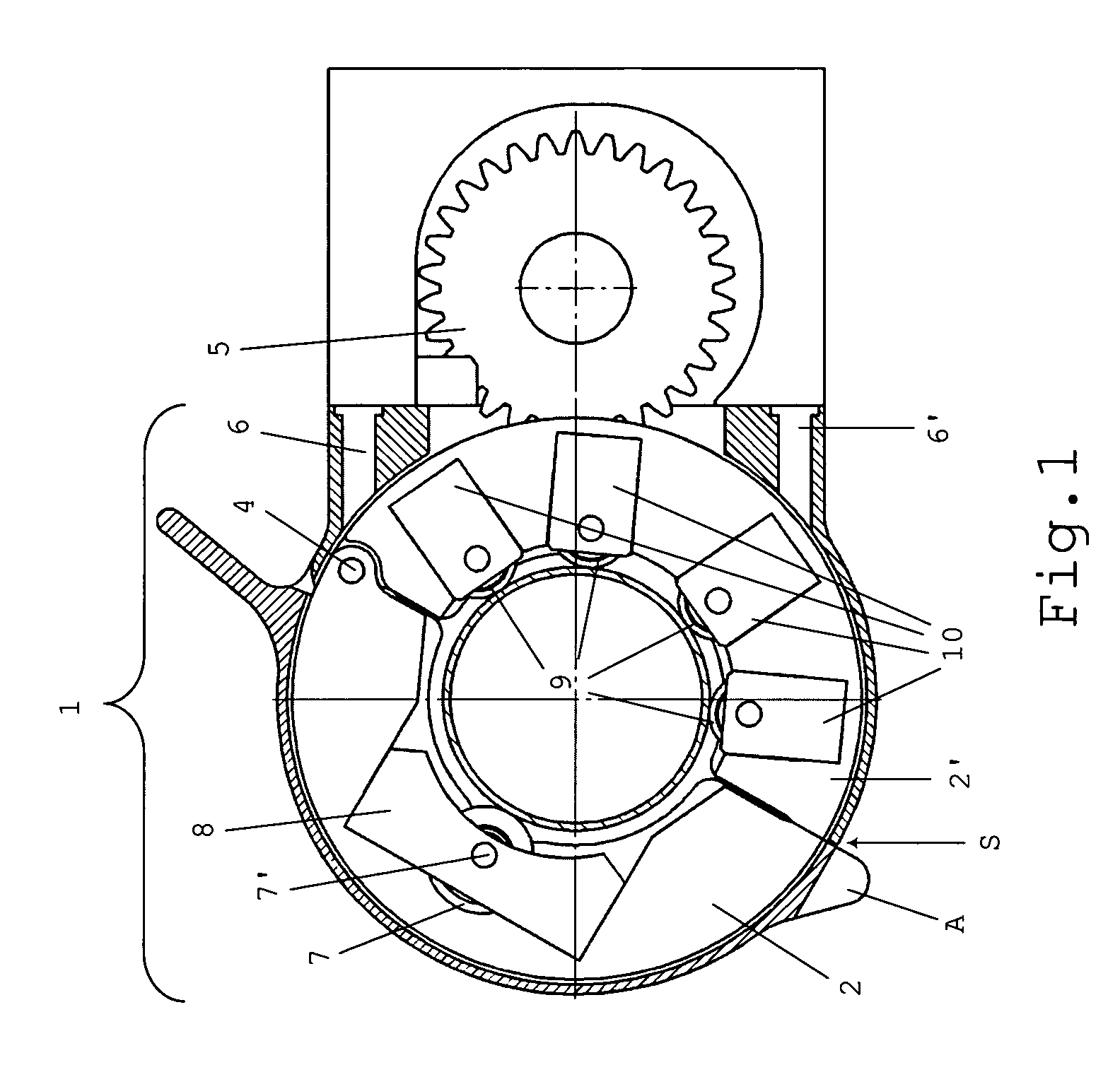
[0026]FIG. 1 shows a section through an embodiment of a tool head 1 according to the invention. A first and second inner jaw 2, 2′, which are connected to one another via a pivot joint 4, form the basic components of the inner head part here. For larger pipe diameters, a plurality of inner jaws can be provided. The outer head part, which likewise has a first and second housing jaw 3, 3′ connected to one another by means of a pivot joint, is recognizable only in rudimentary form. The inner head part is rotatably mounted in a guide in the outer head part and can be driven via a drive device in a direction of rotation in the clockwise or counterclockwise direction.

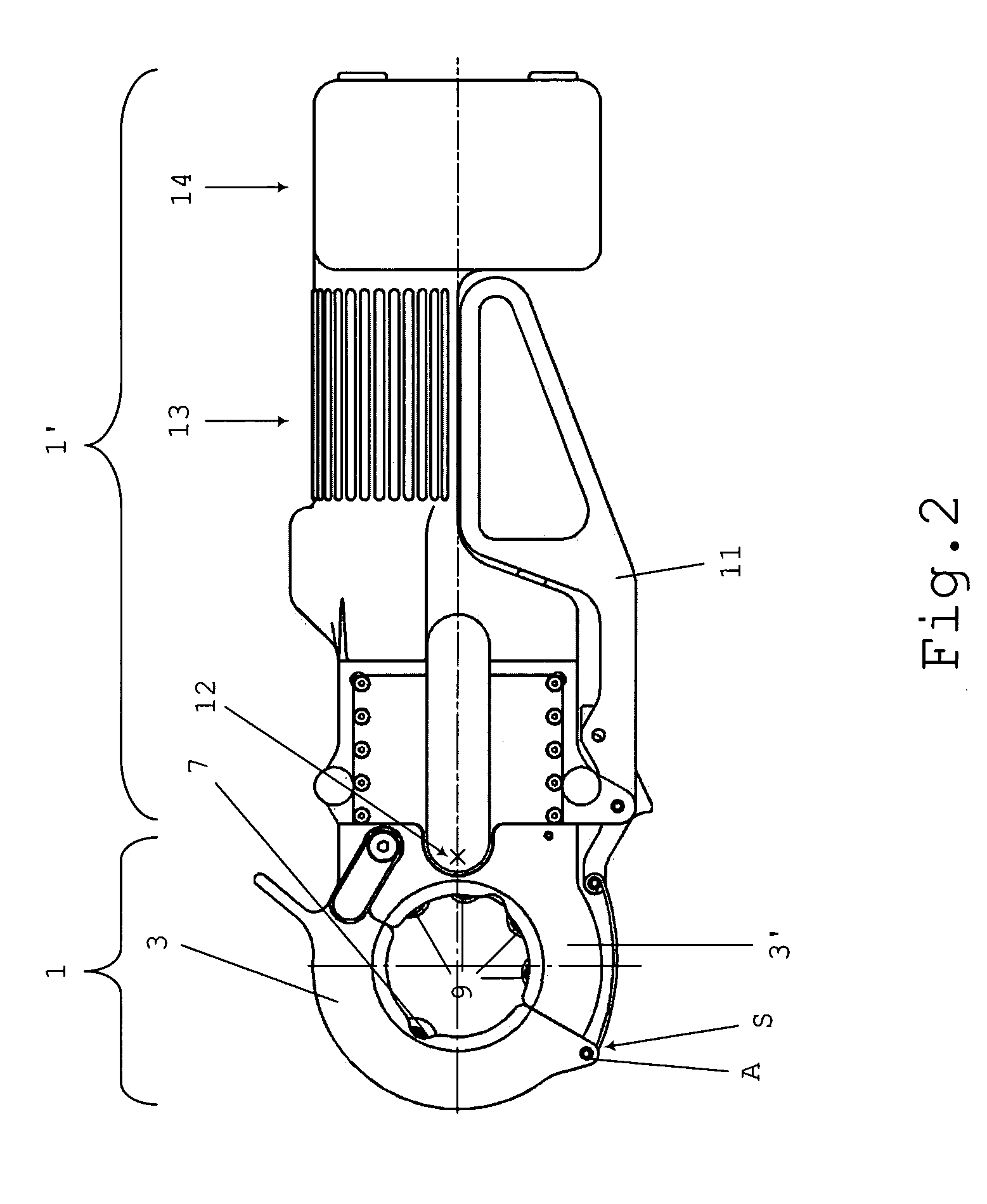
[0027]The drive device is shown only partly in the drawing and, in this working example, comprises a first and second drive ring as a first drive unit and a first and second drive wheel and a motor as a second drive unit. The drive rings are not shown in FIGS. 1 and 2; they are coordinated with the inner head part, for exampl...


PUM

PropertyMeasurementUnit
diametersaaaaaaaaaa
diametersaaaaaaaaaa
sizesaaaaaaaaaa

Abstract

A pipe cutter according to the invention has an inner head part which, in the working position, rotates about a pipe which is clamped in the inner head part and is to be processed. Integrated in the inner head part are a spring-mounted cutting wheel head (8) having a cutting wheel (7) for cutting the pipe and a plurality of support rollers (9) in spring-mounted receptacles (10). The arrangement and formation of cutting wheel (7) and support rollers (9) is such that the clamped pipe is at right angles to the cutting wheel (7), and a right-angled cut is thus achieved. Moreover, a defined feed cutting force can be set by the spring mounting of cutting wheel head (8) and support roller receptacles. During cutting, the pressure on the pipe decreases with increasing cutting depth, and the pipe can thus be cut cleanly and without burrs.

Description

BACKGROUND OF THE INVENTION[0001]1. Field of the Invention[0002]The invention relates to a pipe cutter, and in particular a hand-held pipe cutter.[0003]2. Description of the Background Art[0004]The parting of pipes—also referred to as “cutting into sections”, is often the first step in installation work. The quality of the cutting, i.e. in particular the quality of the cutting edge, is of major importance for subsequent operations, in particular for subsequent joining of cut pipe ends. An important criterion for clean parting—e.g. cutting, sawing or punching—of pipes is a right-angled cut; the pipe must therefore be at right angles to the parting tool, such as a cutting wheel. Furthermore, the stable position of the pipe in the tool and the quality of the tool components, such as of the cutting wheel, and of course the parting process itself play a role with regard to the parting quality.[0005]For the cutting of pipes, pipe cutters have been developed for many years. In particular f...

Claims


Application Information

Patent Timeline
Patent Type & Authority Patents(United States)
IPC IPC(8): B23D21/06
CPCB23D21/04
Inventor GOOP, HANS-JOERG
Owner CEKA ELEKTROWERKZEUGE
Why Eureka
Try Eureka