
Device and method for qualitative determination of the cavitation energy of ultrasound in containers

a technology of qualitative determination and cavitation energy, which is applied in the direction of level indicators by physical variable measurement, liquid/fluent solid measurement, engine lubrication, etc., can solve the problems of difficult direct measurement of cavitation or cavitation energy introduced into the liquid by ultrasound, difficult reproducibility of measuring conditions, and difficult to test cleaning or cavitation power. achieve the effect of simple, reliable and wear-free manner

Inactive Publication Date: 2011-10-11
BANDELIN ELECTRONICS
View PDF13 Cites 2 Cited by
  • Summary
  • Abstract
  • Description
  • Claims
  • Application Information

AI Technical Summary

Benefits of technology

[0014]The object therefore underlying the present invention is to provide a measuring chamber or a method for operation thereof, assessment of the ultrasonic cleaning power being possible via the measurement of a cavitation-caused increase in volume in a simple, reliable and wear-free manner.

Problems solved by technology

The central problem for many users of ultrasound is the requirement to be able to test their cleaning or cavitation power.
Since direct measurability of the cavitation or cavitation energy which is introduced into the liquid by ultrasound is very difficult, alternative methods have been developed.
The reproducibility of the measuring conditions which is not always simple and also the fact that the foil itself changes the sound field in the ultrasonic bath are disadvantageous.
Common disadvantages of these technologies are the dependence of the measuring values upon the respective measuring location and also the sound field change caused by the measuring device itself.
In the case of measurements by hand with single sensors, there is also an individual error component due to changes in position.
In addition, the measured sound pressure offers no information about the cavitation since the context is non-linear to a high degree.
For qualitative assessment of the cleaning power of an ultrasonic bath, they are not suitable.
The method and the required measuring and evaluation technology is very complex and not suitable for a routine testing of ultrasonic baths.

Method used


Image

  • Device and method for qualitative determination of the cavitation energy of ultrasound in containers
  • Device and method for qualitative determination of the cavitation energy of ultrasound in containers

Examples


Embodiment Construction

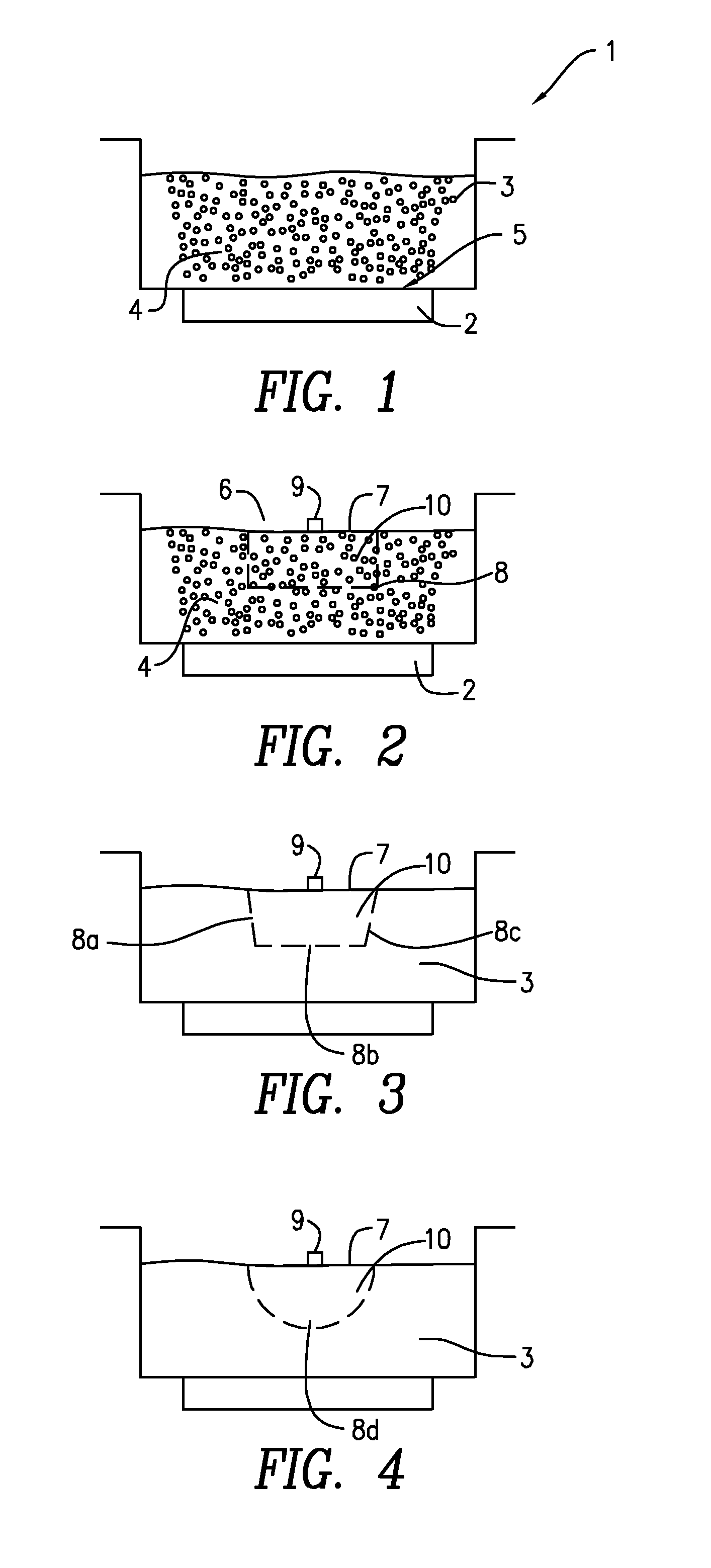
[0039]The invention is explained now with reference to FIGS. 1 to 4.

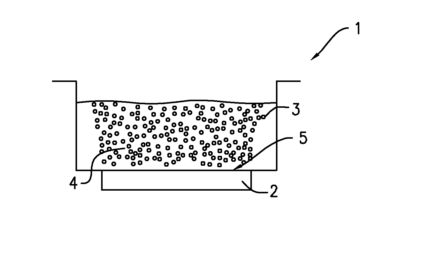
[0040]FIG. 1 shows in a diagram in section a normal ultrasonic bath 1, having a low-frequency ultrasonic source 2, filled with the liquid volume 3 and a cavitation field 4 which has been illustrated by small circles for the sake of simplicity. The ultrasonic bath 1 here is for example an open tub, manufactured for example from stainless steel or plastic material. The ultrasonic source 2—for example a piezoelectric system—is fitted securely here on the base 5 of the ultrasonic bath 1 and is operated by a generator, not shown, with a sufficient HF energy in resonance. During active operation, the low-frequency ultrasonic source 2 generates longitudinal ultrasonic waves which propagate everywhere over the base 5 in the liquid volume 3 and generate an intensive cavitation field 4. The configuration, distribution and intensity of the cavitation occurrences in the cavitation field 4 are thereby irregular and not able to b...


PUM


Abstract

The present invention relates to a measuring chamber (6) for an ultrasonic bath (1) or for a container which is equipped with a low-frequency ultrasonic source (2) for cavitation generation, this measuring chamber being suitable for determining the cavitation energy via the increase in volume in a measuring liquid (10) contained in the measuring chamber, and the measuring chamber having in addition a container (7) with a sound-permeable window region (8) and a sensor (9) for measuring the increase in volume of the measuring liquid (10).In addition, a method for operating this measuring chamber is presented.With the measuring chamber according to the invention or the corresponding method (independent of a prescribed ultrasonic bath), reliable determination of the introduced ultrasonic power or a conclusion about the cleaning power is possible.

Description

BACKGROUND[0001]The invitation relates to a method and to a device for qualitative determination of the cavitation energy in a container, in the liquid volume of which cavitation is initiated by a suitable ultrasonic source. The smallest cavities microscopically are hereby formed constantly and visibly rise coagulating or also implode. As a result of this production of gas or vapour bubbles, cavitation leads to a measurable expansion of the liquid. In order to determine the cavitation energy, a hermetically sealed measuring chamber with a sound-permeable window region is disposed in the container. During operation of the ultrasonic source, the increase in volume of the measuring liquid, initiated by cavitation, can be determined in the measuring chamber with a short-term measurement. The relative increase in volume of the measuring liquid thereby corresponds in a good approximation to the cavitation energy introduced proportionally into the measuring chamber for the container. The c...

Claims


Application Information

Patent Timeline
Patent Type & Authority Patents(United States)
IPC IPC(8): G01F23/28
CPCG01H3/10
Inventor JUNG, RAINER
Owner BANDELIN ELECTRONICS
Learn More