
Grip pressure sensor

a technology of grip pressure sensor and swing, which is applied in the field of grip pressure sensor, can solve the problems of inability to absolutely correct the inherent drawback of the grip being in the form of a glove, and the grip pressure of the swing

Inactive Publication Date: 2011-10-11
CALDWELL THEODORE +1
View PDF50 Cites 30 Cited by
  • Summary
  • Abstract
  • Description
  • Claims
  • Application Information

AI Technical Summary

Benefits of technology

"The patent describes a system that monitors grip pressure using a device that looks like a wrist watch. The device contains a flexible printed circuit called a Tekscan FlexiForce® A201 Sensor that measures force between two surfaces. The system can record and save grip pressure values, and will alert the wearer if they use a different grip pressure. The system can also display the grip pressure on the watch face using arrows indicating a stronger or weaker grip."

Problems solved by technology

One of the more subtle difficulties encountered by most athletes is the grip pressure of the swing.
There is no absolutely correct grip pressure of the swing.
While the glove unit is a highly accurate and desirable device, it has the inherent drawback that it is in the form of a glove.
The glove is not interchangeable to allow use by either a right-handed or left-handed golfer, there is significant variation in sizing and the glove can not be made as durable as the monitoring instrumentation attached to it.

Method used


Image

  • Grip pressure sensor
  • Grip pressure sensor
  • Grip pressure sensor

Examples


Embodiment Construction

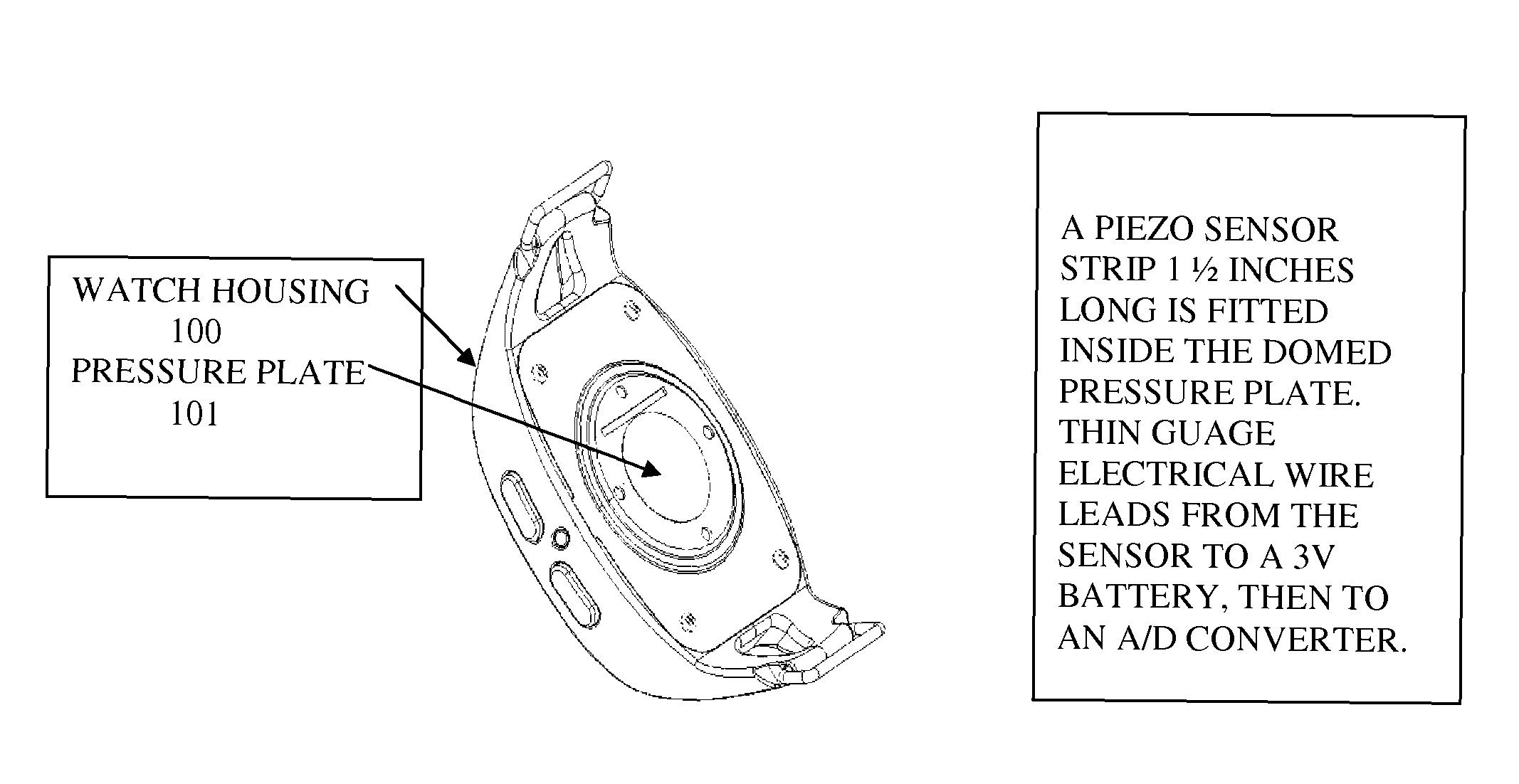
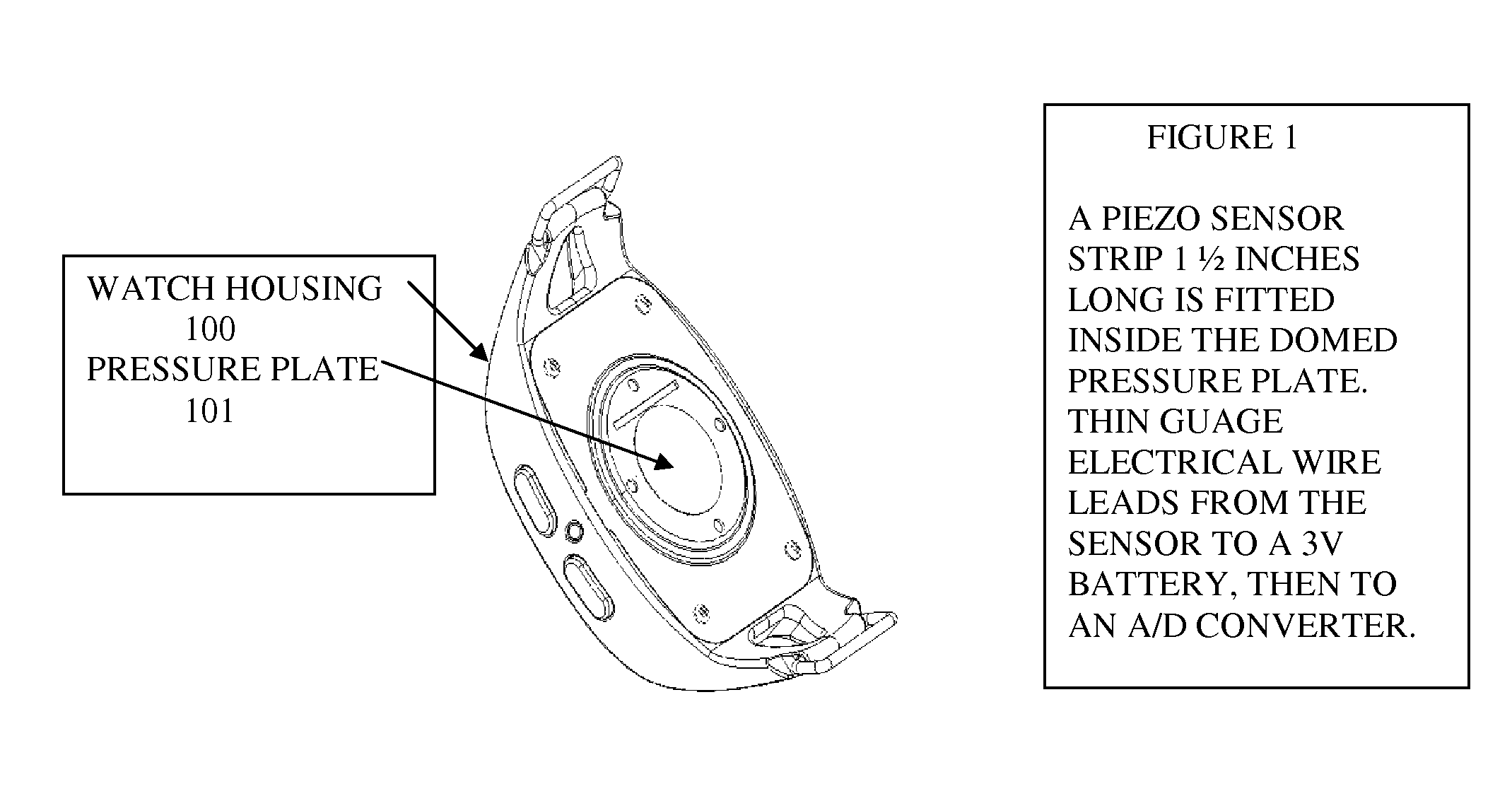
[0015]FIG. 1 is a representation of the outside housing 100 of the instant invention. The watch's back plate, 101 made of thin metal alloy is cinched securely to the wearer's wrist and makes contact with the pulse pressure points. The domed shape of the back plate is pliable. When the muscles and tendons in the wearer's wrist expand and contract as a result of variable grip pressure, the metal plate will similarly respond to the pressure emanating from the wearer's grip.

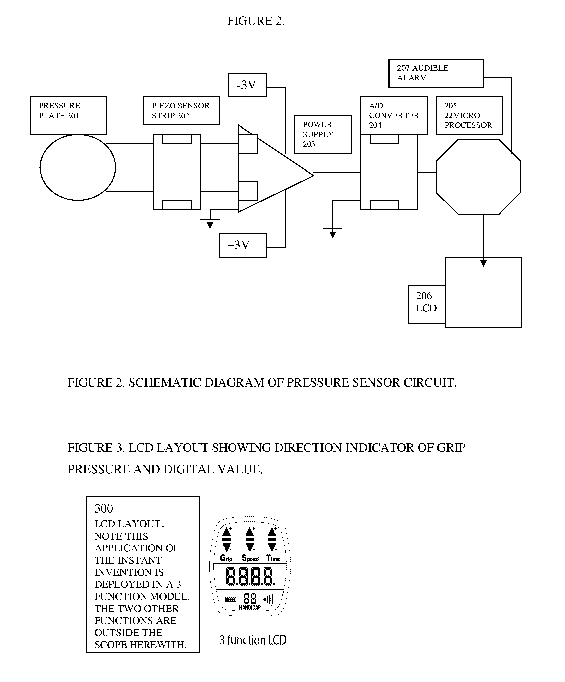
[0016]Inside the housing or watch casement are the various components arrayed in FIG. 2. Two very thin gauge electrical wires lead from a piezo sensor strip 202 and are soldered to the pressure plate 201. The piezo strip registers pressure differentials as the wearer's grip varies when swinging a golf club, cricket bat, squash racquet, or the like. The signal from the piezo sensor is driven by a 3 Volt battery 203 and thence to an A / D converter 204. The numeric values assigned to the corresponding pressure is somewha...


PUM


Abstract

Grip pressure is monitored by a collection of battery powered components embodied in an assembly analogous to an ordinary wrist watch, that is a watch housing or casement and a stretchable band. The system, which we shall refer to as a swing monitor, is worn on the wrist and deployed in such a way that the back of the housing or casement is cinched securely to the back or underside of the wrist. A pressure plate on the back of the watch makes contact with the pulse region of the wrist. The flexing and relaxing of the muscles and tendons of the wearer is read by an electronic pressure sensing device, a piezo sensor. A tighter grip will register greater pressure and a looser grip, less pressure. The device records grip pressure associated with the swing of a golf club, tennis racquest or baseball bat, among other articles of sports equipment meant to be swung. The grip pressure determined to be optimal, that is giving the desired result, can be SAVED in the memory of the swing monitor system. Subsequent swings and their associated grip pressures are compared with the SAVED value of the optimal or best swing. An audible signal alerts the wearer if the grip pressure departs from that registered on the optimal or best swing.

Description

BACKGROUND[0001]1. Field of the Invention[0002]This invention is directed to a swing training or teaching device, in general, and to such a training device in the form wrist watch and strap or band to be worn on the wrist of the user and which incorporates components and assemblies for measuring the grip pressure parameter of the swing.[0003]2. Prior Art Statement[0004]Various sports have developed equipment that until very recently, say the last 25 years, was rather basic, if not primitive. Now that modern technology has come into the sports, the equipment and apparatuses dedicated to the sports are becoming more and more technologically advanced or sophisticated.[0005]Improving one's swing is one of the ways golf, tennis and baseball enthusiasts can increase their proficiency. There are special clubs, bats, and racquets as well as weights, video tapes and many other techniques for utilization during practice sessions. The extant learning devices are primarily based on the feedback...

Claims


Application Information

Patent Timeline
Patent Type & Authority Patents(United States)
IPC IPC(8): A63F13/00A63B67/02
CPCA63B69/0002A63B69/3608A63B69/38A63B2059/0022A63B2209/10A63B2071/0661A63B2071/0663A63B2220/56A63B2220/836A63B2071/0627A63B2060/464
Inventor CALDWELL, THEODORECHEN, NING
Owner CALDWELL THEODORE
Learn More