Timepiece

a timepiece and time-piece technology, applied in the field of timepieces, to achieve the effect of improving the accuracy of the timepiece and reducing the fluctuation of the torqu

Active Publication Date: 2011-10-18
LANGE UHREN
View PDF17 Cites 12 Cited by
  • Summary
  • Abstract
  • Description
  • Claims
  • Application Information

AI Technical Summary

Benefits of technology

[0005]These torque fluctuations are substantially eliminated by the tensioning mechanism, whereby the accuracy of the timepiece is improved. As a result of the control system of the tensioning mechanism, the driving part of the clockwork movement does not move uniformly, but in angular steps. The size of these steps is defined by the transmission ratio of the respective gear mechanism. The time intervals are determined by the control system of the tensioning mechanism. The driven part is driven by the storage hairspring and moves substantially uniformly.
[0008]The cyclic steps for tensioning the hairspring, which are generated by the tensioning control system, can thus be used for other functions that are controlled in cyclic steps. This leads to a reduction in the necessary installation space.
[0014]In one embodiment, further auxiliary devices are driven by the minute pinion, such as, for example, a minute repeat mechanism, or an alarm mechanism that can be triggered accurately to the minute.
[0016]A one-handed timepiece can thus be realized, which maintains the ageless and calming character of such a timepiece and nevertheless allows the time to be read down to a few seconds.
[0032]In one embodiment, the impulse pin on the first spindle can be adjustable twistably about the first spindle. This is possible with simple construction by virtue of the fact that the impulse pin is connected to the first spindle by means of a friction coupling.
[0034]In one embodiment, at the free end of the first arm of the lever, in a parallel plane to the fork, a blade part is provided, which extends in the direction of longitudinal extent of the lever and, while the fork is free from action by the impulse pin, bears with its free end against a cam connected in a rotationally secure manner to the impulse pin, then an untimely movement of the lever, triggered by vibrations, is prevented.

Problems solved by technology

As a result of the control system of the tensioning mechanism, the driving part of the clockwork movement does not move uniformly, but in angular steps.

Method used


Image

  • Timepiece
  • Timepiece
  • Timepiece

Examples


Embodiment Construction

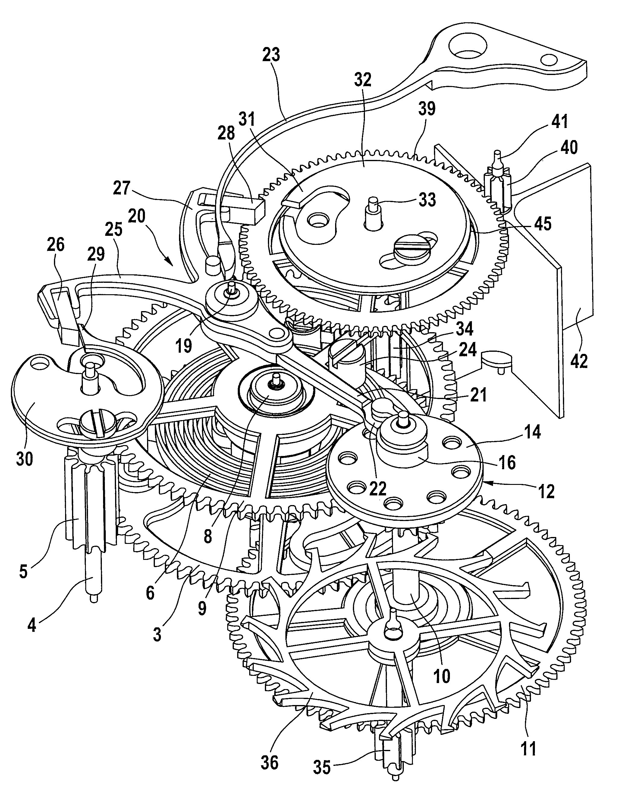
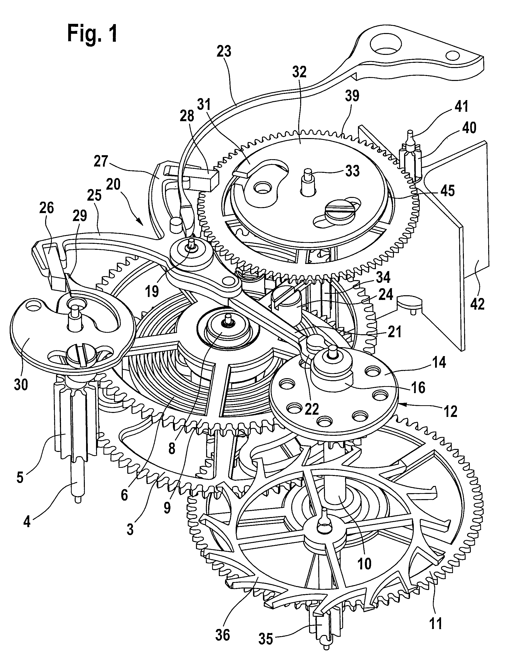
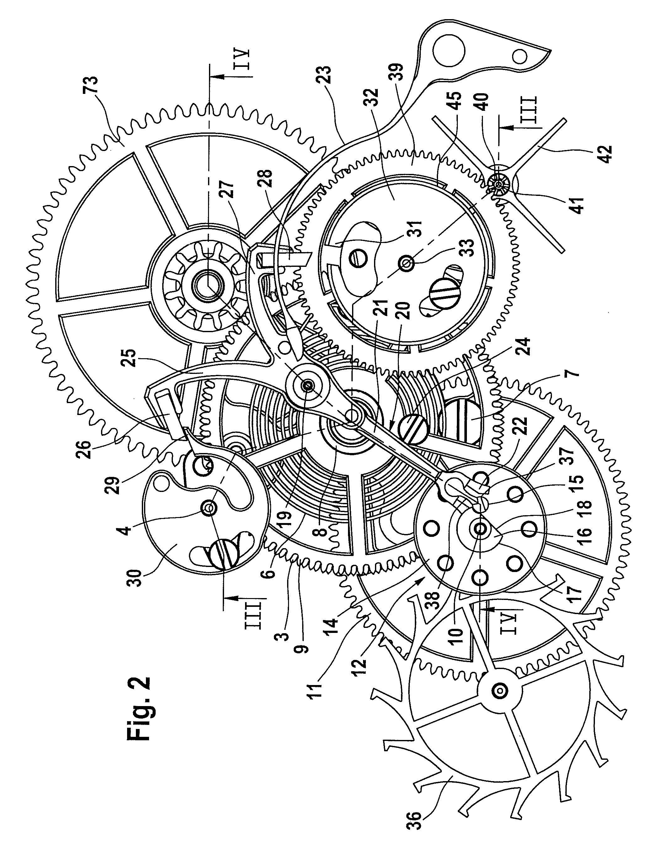
[0052]The tensioning mechanism depicted in FIGS. 1 to 10 has a drive spindle 1, which is preferably driven rotatably in cyclic steps by a mainspring (not shown) of a barrel 48 (shown schematically in FIGS. 12-14).

[0053]Fixedly disposed on the drive spindle 1 is a pinion 2, by which a minute wheel 73 is rotatably driven.

[0054]A first third wheel 3 is likewise fixedly disposed on the drive spindle 1 and engages with a drive wheel 5 disposed on a second spindle 4 parallel to the drive spindle 1.

[0055]Arranged around the drive spindle 1 is a storage hairspring 6 that is connected at its outer ends, by means of an outer spiral fastener 7, to the first third wheel 3.

[0056]The storage hairspring 6 is fixedly connected at its inner end to a hub 8 of a second third wheel 9, which by means of the hub 8 is mounted rotatably on the drive spindle 1.

[0057]By means of the second third wheel 9, first spindle 10, bearing a second wheel 11, is driven in a continuously rotatable manner. The second whe...


PUM


Abstract

A timepiece comprising a main energy storing device, a gear train coupled to the main energy storing device, a tensioning element coupled to the gear train, the tensioning element configured to be driven about a tensioning axis in cyclic steps, a tensioning control system configured to control the tensioning element, a storage hairspring having a first end and a second end, the first end connected to the tensioning element, a wheel connected to the second end of the storage hairspring, a clockwork movement rotatably driven by the wheel, an escapement coupled to the clockwork movement and a device configured to be switched in a stepwise manner and driven rotatably in cyclic steps by an element of the gear train.

Description

BACKGROUND OF THE INVENTION[0001]1. Field of the Invention[0002]The invention relates to a timepiece, in particular to a watch, with a main energy-storing device, by means of which a tensioning element of a tensioning mechanism can be driven via a gear train in a rotatable manner about a tensioning axis controlled in cyclic steps by means of a tensioning control system that tensions a storage hairspring connected at one end to the tensioning element, the other end of the storage hairspring is connected to a wheel which rotatably drives the clockwork movement and is in engagement with the gear mechanism of the escapement.[0003]2. Description of the Related Art[0004]In timepieces, the storage hairspring is tensioned by the same amount, at equal-sized time intervals defined by the mechanism. The oscillating system of the timepiece is thus supplied with a constant torque that is required if the main energy-storing device is subject to large torque fluctuations. The cause of the torque f...

Claims


Application Information

Patent Timeline
Patent Type & Authority Patents(United States)
IPC IPC(8): G04B15/00G04B23/00G04B19/02
CPCG04B15/10
Inventor SCHNEIDER, JENS
Owner LANGE UHREN
Why Eureka
Try Eureka