Power transmission chain, and power transmission system having the same

a technology of power transmission chain and power transmission system, which is applied in the direction of belt/chain/gearing, driving belt, chain element, etc., can solve the problems of undesirable noise or wear of pin end faces, undesirable amplitude, and inability to adjust the vibration of the chain according to the direction of the driving belt, etc., to achieve excellent quietness, durability and transmission efficiency.

Inactive Publication Date: 2011-10-18
JTEKT CORP
View PDF22 Cites 4 Cited by
  • Summary
  • Abstract
  • Description
  • Claims
  • Application Information

AI Technical Summary

Benefits of technology

[0016]According to the invention, the frictional resistance between the links pressed to contact acts as the damping force at the time of vibrations of the power transmission chain thereby to suppress the vibrations reliably. As a result, the power transmission parts can be prevented from impactive contact with the pulleys thereby to improve the quietness and the durability. Moreover, the frictional resistance is caused only in some of the links so that the drive loss is small. Moreover, the power transmission parts, as clamped in engagement with the pulleys, receive the pushing forces of the pulleys from the two end portions, and are bent so that the two end portions are seriously warped. However, the links pushed to contact with each other are selectively disposed at the predetermined area, in which the pressure transmission members are less warped. As a result, it is possible to prevent the links pushed to contact from having their relative positions accidentally fluctuated to excessively contact with each other thereby to prevent the frictional resistances between those links from becoming excessively high. The drive loss can be reliably reduced to achieve high transmission efficiency.
[0021]In this case, the links are fixed in the corresponding first and second power transmission parts so that they can be positioned in the chain width directions. As a result, the links can be reliably pushed to contact with each other.
[0022]According to the invention, there may be provided a power transmission system may include: first and second pulleys individually including a plurality of conical sheave faces confronting each other; and the aforementioned power transmission chain looped between the pulleys and engaging with the sheave faces for transmitting a power. In this case, it is possible to realize the continuously variable transmission, which is excellent in quietness, durability and transmission efficiency.

Problems solved by technology

However, the chord vibrations may occur according to the moving conditions.
In this case, the pins are impulsively brought into contact with the pulleys to cause noises or the wears of pin end faces undesirably.
Especially if the frequency of the chord vibrations coincides with the natural frequency of the power transmission chain, the amplitude becomes undesirably large.
In JP-A-2005-214323 and JP-A-2005-214345, however, the bending torque of the power transmission chain is reduced to have a low resistance to the damping of the chord vibrations so that the chord vibrations are hard to suppress once they occur.
If the links are merely brought into the frictional contact, however, the loss at the bending time is increased to drop the transmission efficiency drastically.

Method used


Image

  • Power transmission chain, and power transmission system having the same
  • Power transmission chain, and power transmission system having the same
  • Power transmission chain, and power transmission system having the same

Examples


Embodiment Construction

[0030]A preferred mode of embodiment of the invention is described with reference to the accompanying drawings.

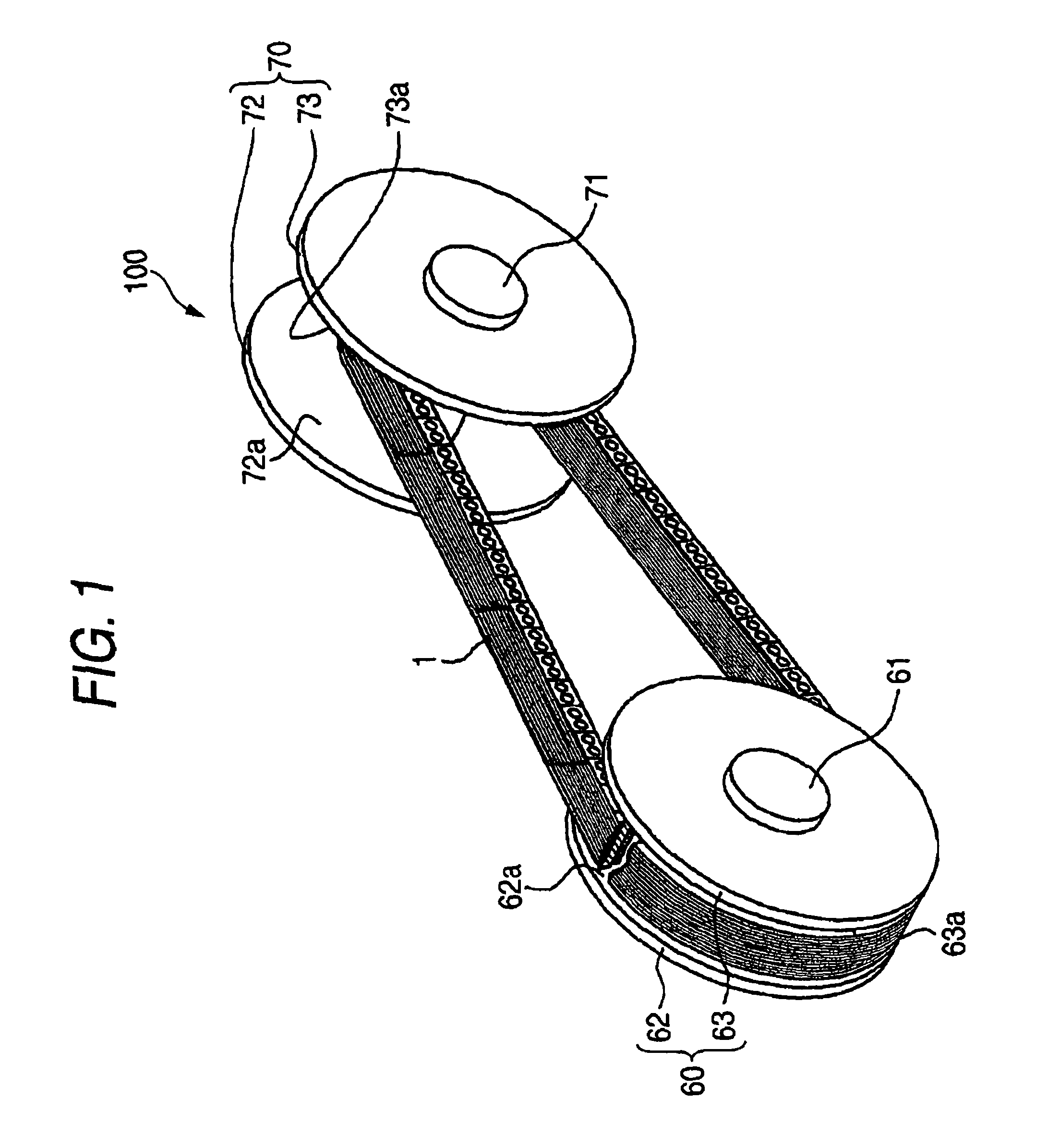
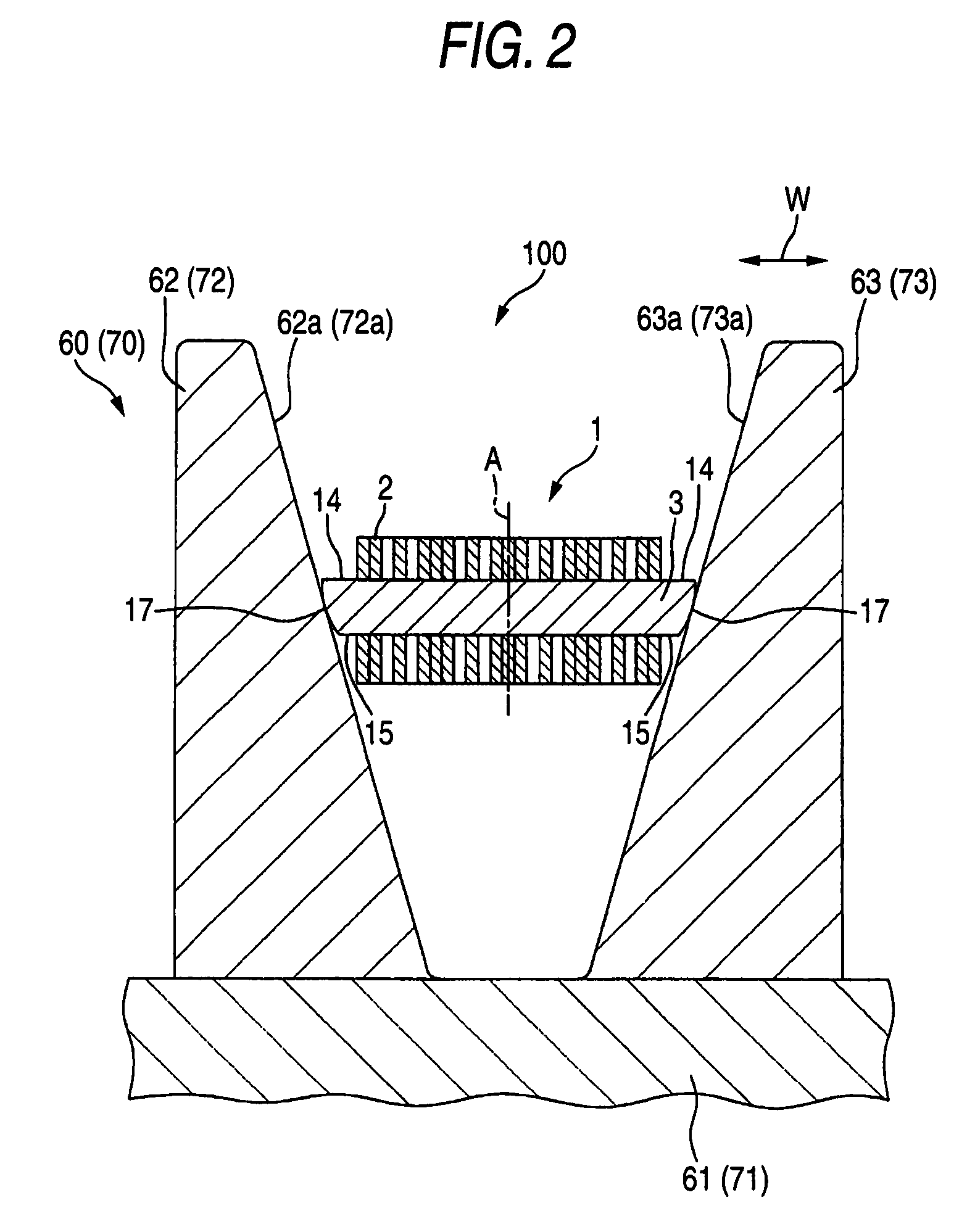
[0031]FIG. 1 is a perspective view schematically showing a constitution of an essential portion of a chain type continuously variable transmission (as will be shortly referred to as the “continuously variable transmission”) acting as a power transmission system, which is provided with a power transmission chain according to one mode of embodiment of the invention. With reference to FIG. 1, a continuously variable transmission 100 is mounted on a vehicle such as an automobile, and is provided with: a drive pulley 60 made of a metal (e.g., structural steel) as a first pulley; a driven pulley 70 made of a metal (e.g., structural steel) as a second pulley; and an endless power transmission chain 1 (as will be shortly referred to as the “chain”) looped between those two pulleys 60 and 70. Here, the chain 1 is presented partially in section in FIG. 1 so that it may be easily unde...


PUM


Abstract

A chain is provided with a plurality of links, and connecting members for connecting those links such that the links are relatively bendable to each other. A first pin of the connecting member is clamped between pulleys thereby to transmit the power between itself and said pulleys. The chain includes a central area with respect to chain width directions, and side areas located on the sides of the central area. In the central area, links adjoining in the chain width directions are pushed to contact with each other, and rotate relative to each other while exerting frictional forces on each other as the chain is bent. In each of the side areas, the links adjoining in the chain width directions are arrayed through a predetermined clearance.

Description

BACKGROUND OF THE INVENTION[0001]1. Field of the Invention[0002]The present invention relates to a power transmission chain and a power transmission system provided with the chain.[0003]2. Related Art[0004]An endless power transmission chain to be used in a power transmission system such as a pulley type continuously variable transmission (CVT) of an automobile is provided with a plurality of links, and pins connecting those links, so that the paired end faces of the pins individually engage with the taper disks of pulleys thereby to transmit the power between themselves and the pulleys (as referred to JP-A-2005-214323 and JP-A-2005-214345, for example).[0005]In the power transmission chain of JP-A-2005-214323, with the links being superposed in the thickness direction, pins are press-fitted in the pinholes of those links, and the links arranged to adjoin each other are bendably connected to each other. These adjoining links make frictional contact at their side faces with each othe...

Claims


Application Information

Patent Timeline
Patent Type & Authority Patents(United States)
IPC IPC(8): F16G5/16F16G13/04F16G1/21
CPCF16G5/18
Inventor YASUHARA, SHINJI
Owner JTEKT CORP
Why Eureka
Try Eureka