Removable electronic drum head for an acoustic drum

a drum head and electronic technology, applied in the field of electronic and acoustic drums, can solve the problems of difficult recording using a microphone, large electronic drum kits, and limited sound types of acoustic drums, and achieve the effects of minimizing acoustic noise from the kit, saving a lot of space, and easy attachment and removal

Active Publication Date: 2011-10-18
INMUSIC BRANDS
View PDF36 Cites 33 Cited by
  • Summary
  • Abstract
  • Description
  • Claims
  • Application Information

AI Technical Summary

Benefits of technology

[0008]The present invention solves the problems of the prior art by providing an electronic drum head that fits on top of a drummer's existing acoustic drums. When the drummer plays these heads, the drum head is muted, minimizing acoustic noise from the kit. Also, these electronic drum heads can be easily attached and removed, allowing the drummer to go back to playing his acoustic drums when desired. A separate electronic drum kit is not necessary,

Problems solved by technology

Professional drummers face a number of problems with their chosen instrument because acoustic drum kits are generally large and take up a lot of space and are very loud when played.
Acoustic drums are also limited in the types of sounds they are capable of producin

Method used


Image

  • Removable electronic drum head for an acoustic drum
  • Removable electronic drum head for an acoustic drum
  • Removable electronic drum head for an acoustic drum

Examples


first embodiment

[0021]An optional addition to the first embodiment is a rimshot sensor 24. Preferably, the rimshot sensor 24 is a membrane switch or Force Sensing Resistor (“FSR”) aligned along the outer edge of the drum head.

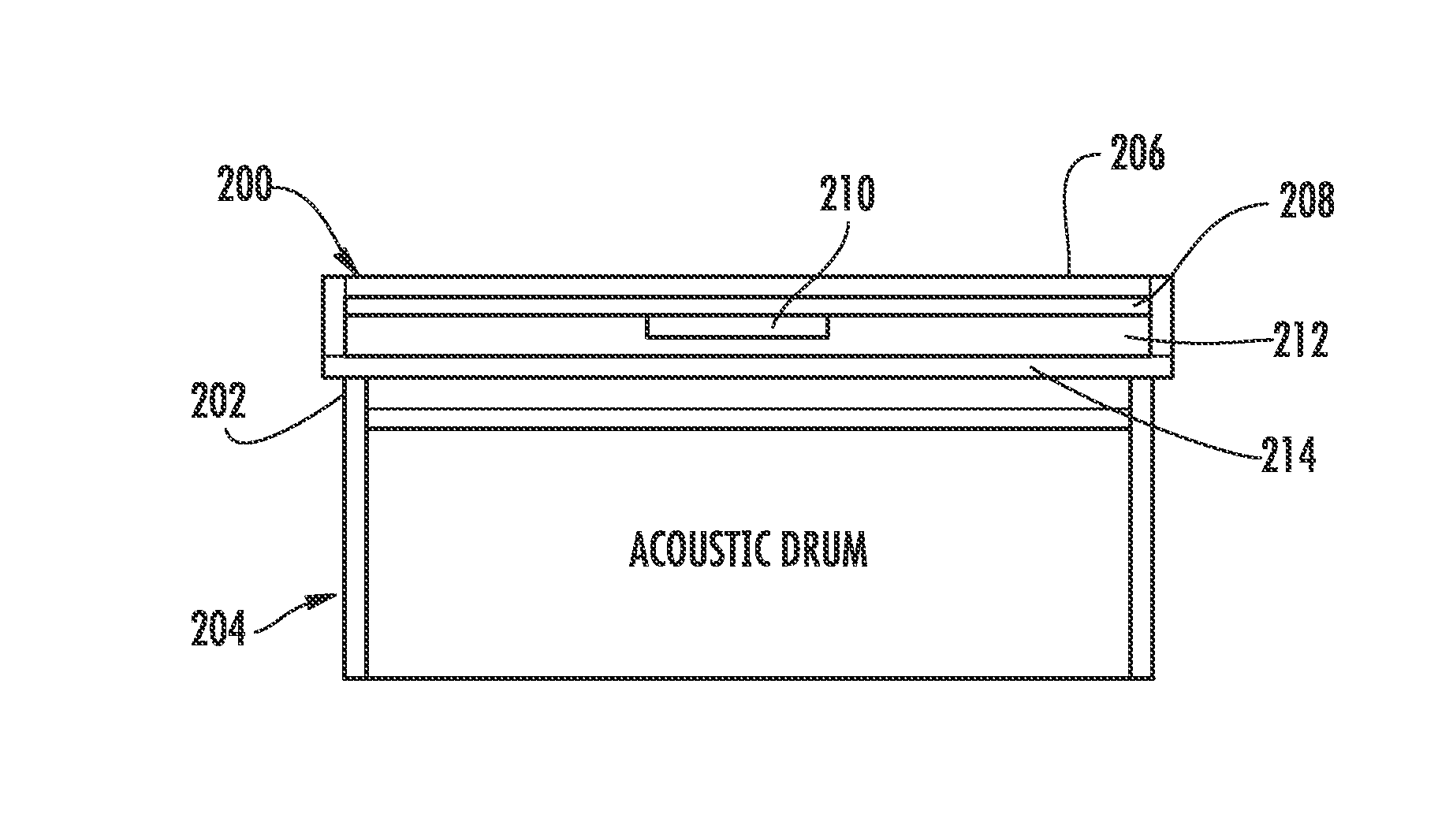
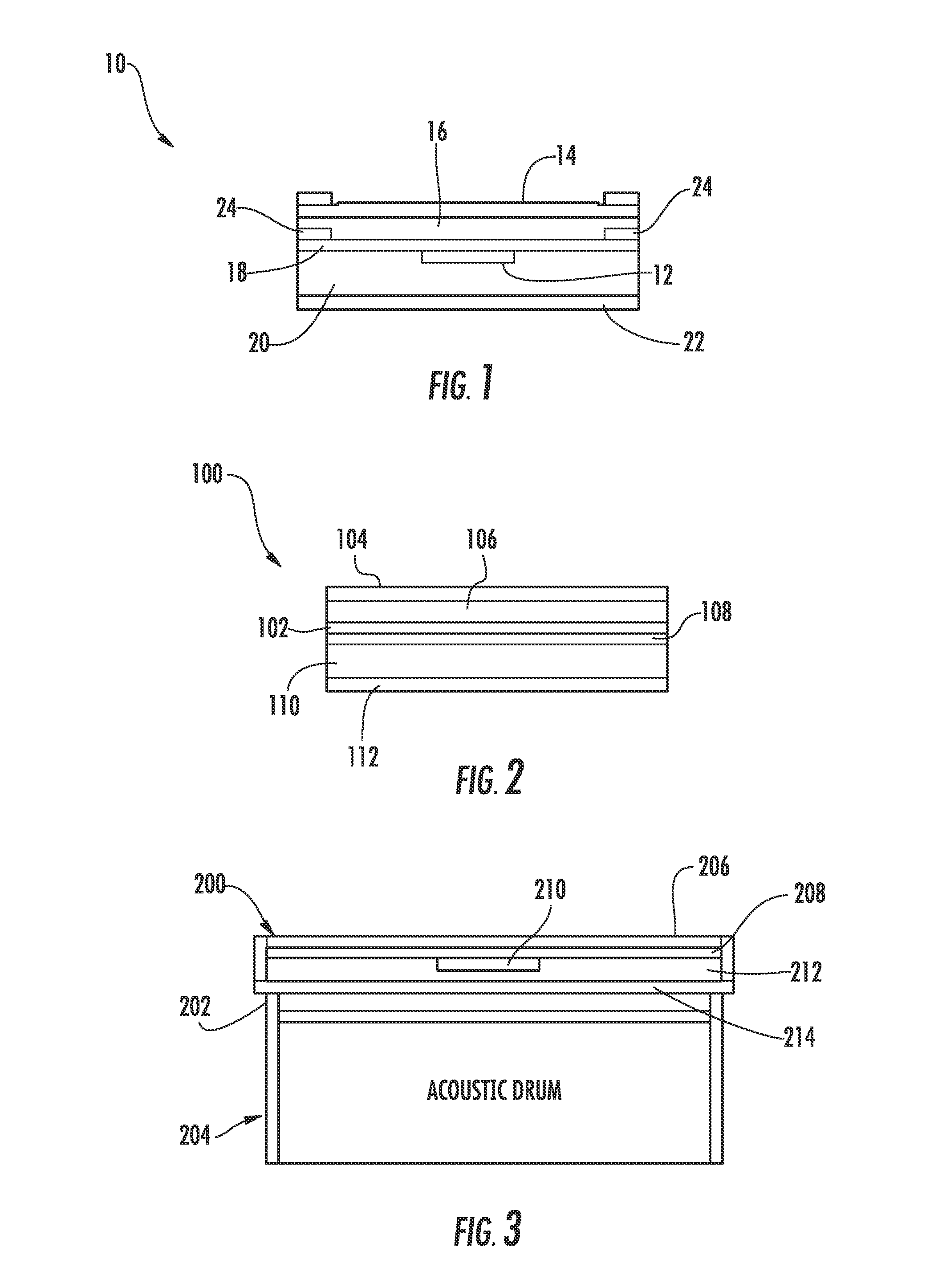
[0022]Referring now to FIG. 2, the second embodiment 100 also includes a sensor 102 to detect drumstick strikes. For the sensor 102, the second embodiment relies principally on a membrane switch or FSR to detect the drum strikes. The top layer 104 is an elastic or resilient layer to absorb the strike of the drumstick. The top elastic layer 104 can be formed from any number of artificial or natural rubber compounds. Beneath the top layer is an optional layer 106 of foam, rubber, or other elastic material to further absorb and muffle the impacts of a drumstick. Underneath the optional foam layer, the next layer is the sensor 102. Supporting the sensor, the next layer is a flat rigid plate 108, usually made of metal, but could be made of plastic or other hard material. Supporting...

second embodiment

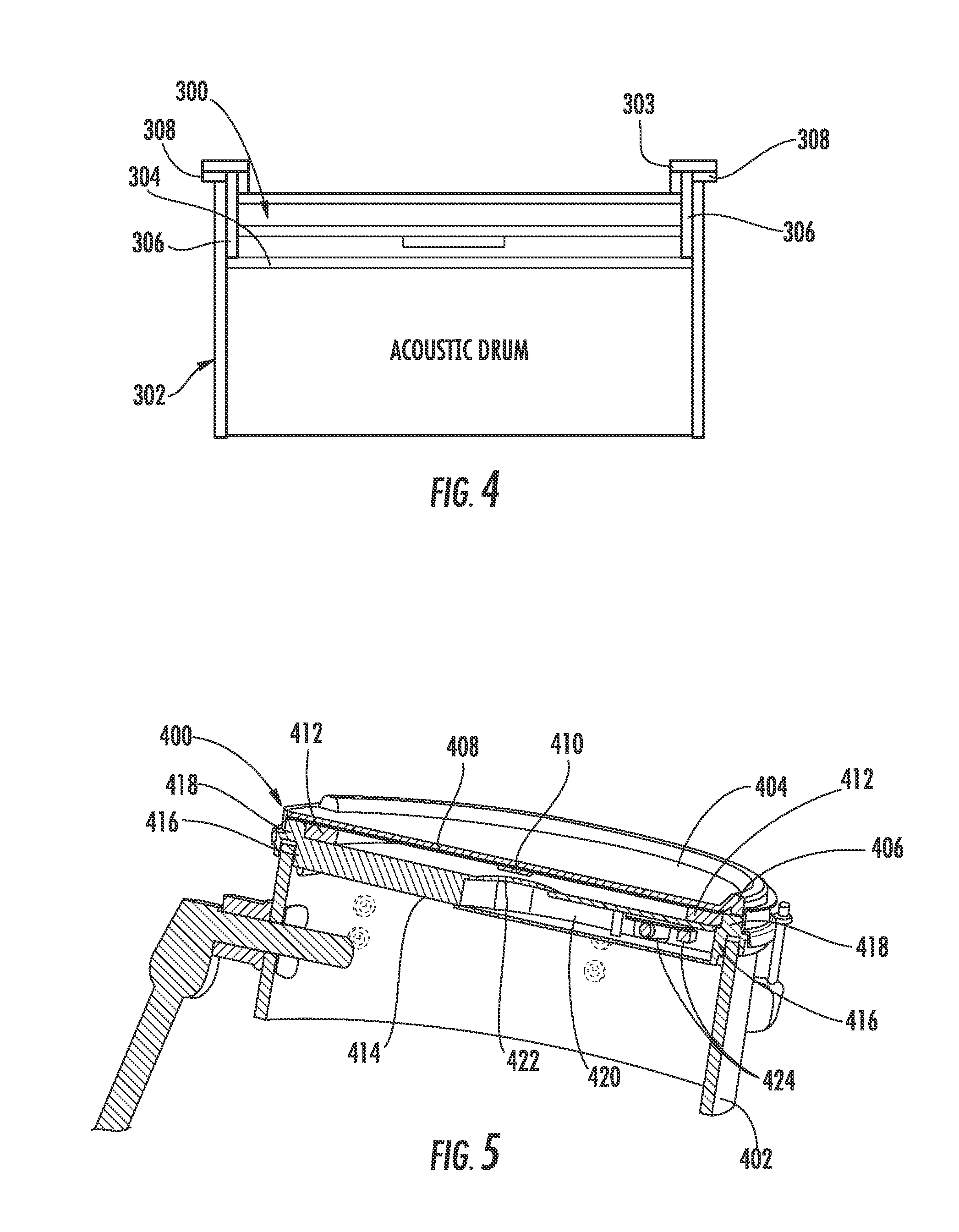
[0028]Turning now to FIG. 4, the electronic drum head 300 may also be clamped down into the acoustic drum 302 by the acoustic drum head 303 and hardware. The electronic drum head 300 consists of a rigid tray 304 with a sidewall 306 and lip 308 extending outwardly from the top edge of the sidewall. The rigid tray 304 contains the layers of elastic material and the sensor. With the acoustic drum head 303 removed, the rigid tray 304 is placed in the acoustic drum 302 and suspended inside the acoustic drum 302. The lip 308 rests against the body of the acoustic drum 302. The acoustic drum head 303 is placed over this, and clamped into place, thereby trapping the electronic drum head 300 securely between the body of the drum 300 and the rim of the drum head 303.

[0029]This method has the advantage that the drummer is able to use the acoustic drum head 303 as the playing surface, which drummers are accustomed to hitting. The disadvantage, however, is that this method takes longer to instal...

third embodiment

[0030]Referring now to FIGS. 5 and 6, in a third embodiment, the electronic drum head 400 replaces the acoustic drum head completely. As earlier, the electronic drum head 400 is held in place by the acoustic drum hoop 402. However, the acoustic drum head (not shown) is not placed over the electronic drum head 400 in this embodiment. The electronic drum head 400 includes an elastic strike layer 404, which may include a raised rim 406 for rimshots. Beneath the strike layer 404 is a rigid plate 408. An optional foam layer (not shown, but see FIG. 1, 2 or 4) may be included between the strike layer 404 and rigid plate 408. A sensor 410 is attached to the bottom surface of the rigid plate 408. A supporting foam ring 412 supports the rigid plate 408 and elastic layer 404. A structural body 414 supports the supporting foam ring 412 and other layers. The structural body 414 includes a sidewall 416 and a lip 418 which are configured to nestle on the acoustic drum hoop 402. The electronic dru...


PUM


Abstract

A removable electronic drum head for an acoustic drum is disclosed. The electronic drum head includes an elastic strike layer, a rigid plate centered below the elastic strike layer. A first sensor is attached to a bottom surface of the rigid plate. A structural body supports the elastic strike layer, rigid plate and first sensor. The structural body is further adapted to attach to an acoustic drum. Other optional foam layers may be included above and below the rigid plate.

Description

CROSS-REFERENCE TO RELATED APPLICATIONS[0001]The present patent document claims priority to earlier filed U.S. Provisional Patent Applications Nos. 61 / 098,062, filed on Sep. 18, 2008 and 61 / 144,279, filed on Jan. 13, 2009, the entire contents of which are incorporated herein by reference.BACKGROUND OF THE INVENTION[0002]1. Field of the Invention[0003]The present patent document relates generally to electronic and acoustic drums and more specifically to a removable electronic drum head that can be attached to a conventional acoustic drum.[0004]2. Background of the Related Art[0005]Professional drummers face a number of problems with their chosen instrument because acoustic drum kits are generally large and take up a lot of space and are very loud when played. Acoustic drums are also limited in the types of sounds they are capable of producing. Additionally, acoustic drums are difficult to record using a microphone.[0006]To solve some of these problems, the electronic drum kit was inv...

Claims


Application Information

Patent Timeline
IPC IPC(8): G10H1/32
CPCG10H3/146G10H2220/561G10H2220/525
Inventor NORMAN, JAMESSHIM, BRIANWISSMULLER, JAN
Owner INMUSIC BRANDS
Why Eureka
Try Eureka