Linear actuator

a technology of linear actuators and actuators, applied in mechanical control devices, dynamo-electric machines, limiting/preventing/returning movement of parts, etc., can solve problems such as counting errors, and achieve the effect of simple and compatible length and simple definition of stroke length

Active Publication Date: 2011-10-18
LINAK AS
View PDF13 Cites 20 Cited by
  • Summary
  • Abstract
  • Description
  • Claims
  • Application Information

AI Technical Summary

Benefits of technology

[0017]In the example, the length of stroke is referred to as “S” and the travel of the spindle nut from the physical end stop is referred to as “L”, which is expressed in the micro processor by the counted number of pulses over the travel of the spindle nut from the physical end stop. The micro processor initially values the output highly and makes use of an intern clock frequency as trigger signal for a counter, incriminating itself for each trigger pulse. It is always compared the number “L”. When the number “L” is reached, the output is valued low and the counting continues until the number “S” is reached, where after the procedure is repeated. As expression for the position of the spindle nut on the length of stroke, a pulse modulated signal can now be obtained, where the duty-cycle directly expresses the position of the spindle nut in proportion to the full length of stroke. This signal is lead through a low-pass filter in order to become a mean value and appear as a DC voltage. As can be experienced, an outer unit would not be able to tell whether this or a solution with a potentiometer was used in the actuator, but the solution described here is both cheaper and sturdier. By a possible replacement of a defective part, using a potentiometer with a new part using the solution described in the invention, full compatibility will be obtained.
[0018]That the example mentions an output, which accurately correspond to what can be expected when using a potentiometer, namely a DC voltage, does not exclude that the position determination can be expressed differently. It would be obvious for interface between more micro processors, directly to continue the fraction expressing the position compared with the length of stroke or as pulse width modulated signal (PVM). A standardized interface could also be used like for instance RS232 between micro processor and other equipment, which further requires a prearranged protocol for transmitting and receiving data. Other interfaces by means of light and optical connections may also be envisaged used. Interfaces, which are frequently used in industrial equipment where a current or voltage is converted into a frequency modulated signal, are also not excluded. (Here, meaning the use of VF converters.)
[0019]By known actuators a determination of the position and the length of stroke in that the end stop switches are mounted on a strip of printed circuit board with a row of holes where the end stop switches can be mounted for fulfillment of the concrete specifications. Actuators with movable end stops are known from DE 89 03 603 to Dewert and WO 02 / 102205 A1 to Cimosys. Anyhow, it is very elaborate to adjust the position and the length of travel of the activation element. By invention it is however relatively simple to redefine the length of stroke and its position, at any time, as a renewed initiating procedure on the new specifications just needs to be done.
[0020]A linear actuator according to the invention will be explained more fully below with reference to the accompanying, drawings.

Problems solved by technology

Here a possible manual adjustment could result in counting errors.

Method used


Image

  • Linear actuator
  • Linear actuator
  • Linear actuator

Examples


Embodiment Construction

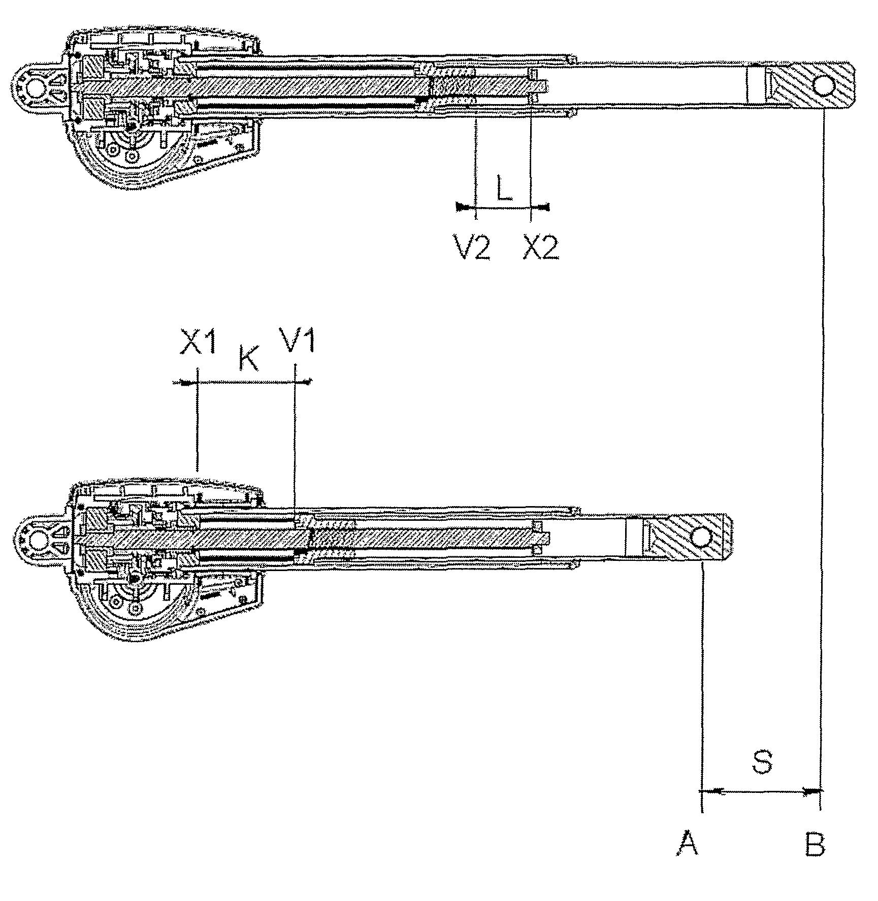
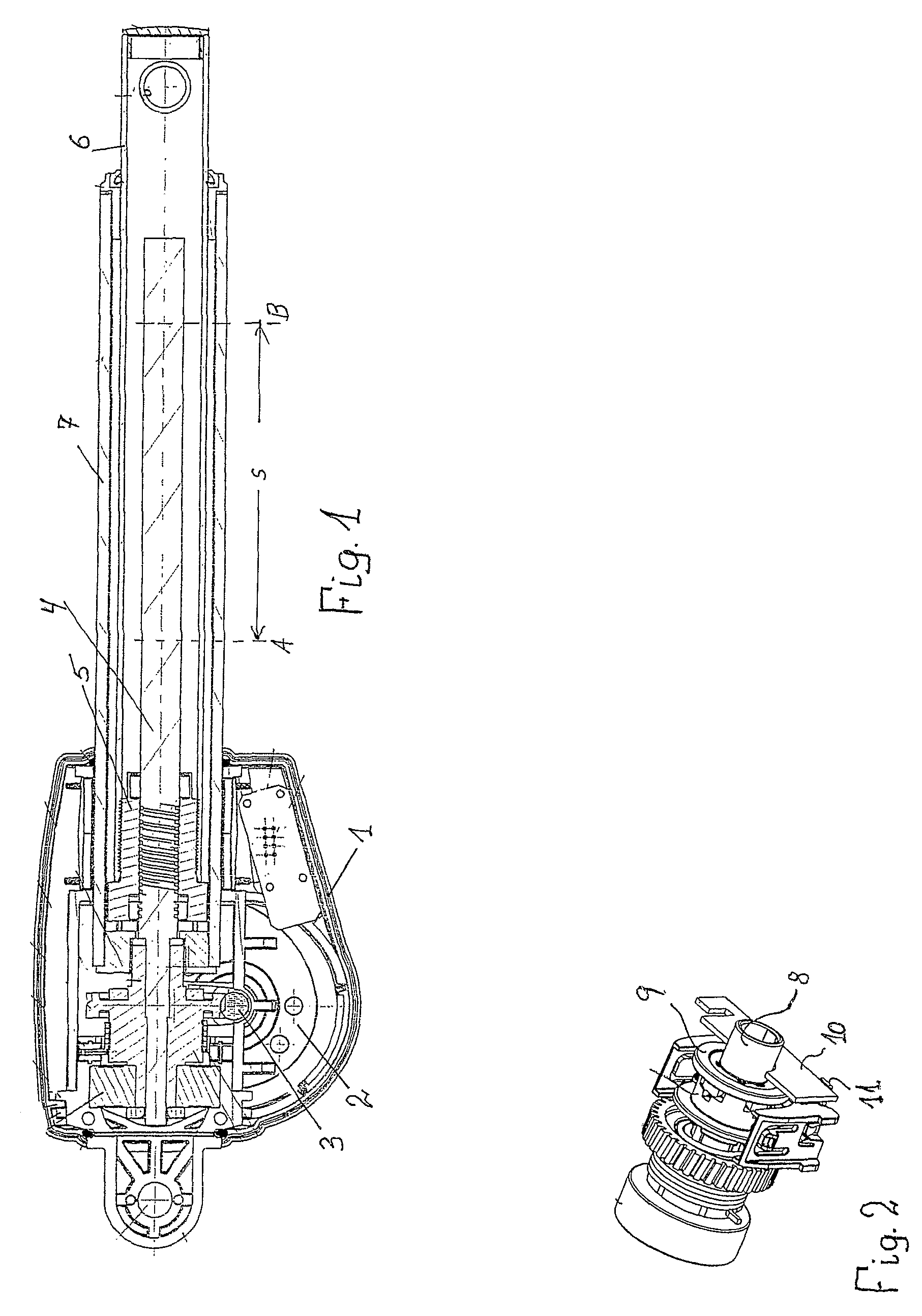
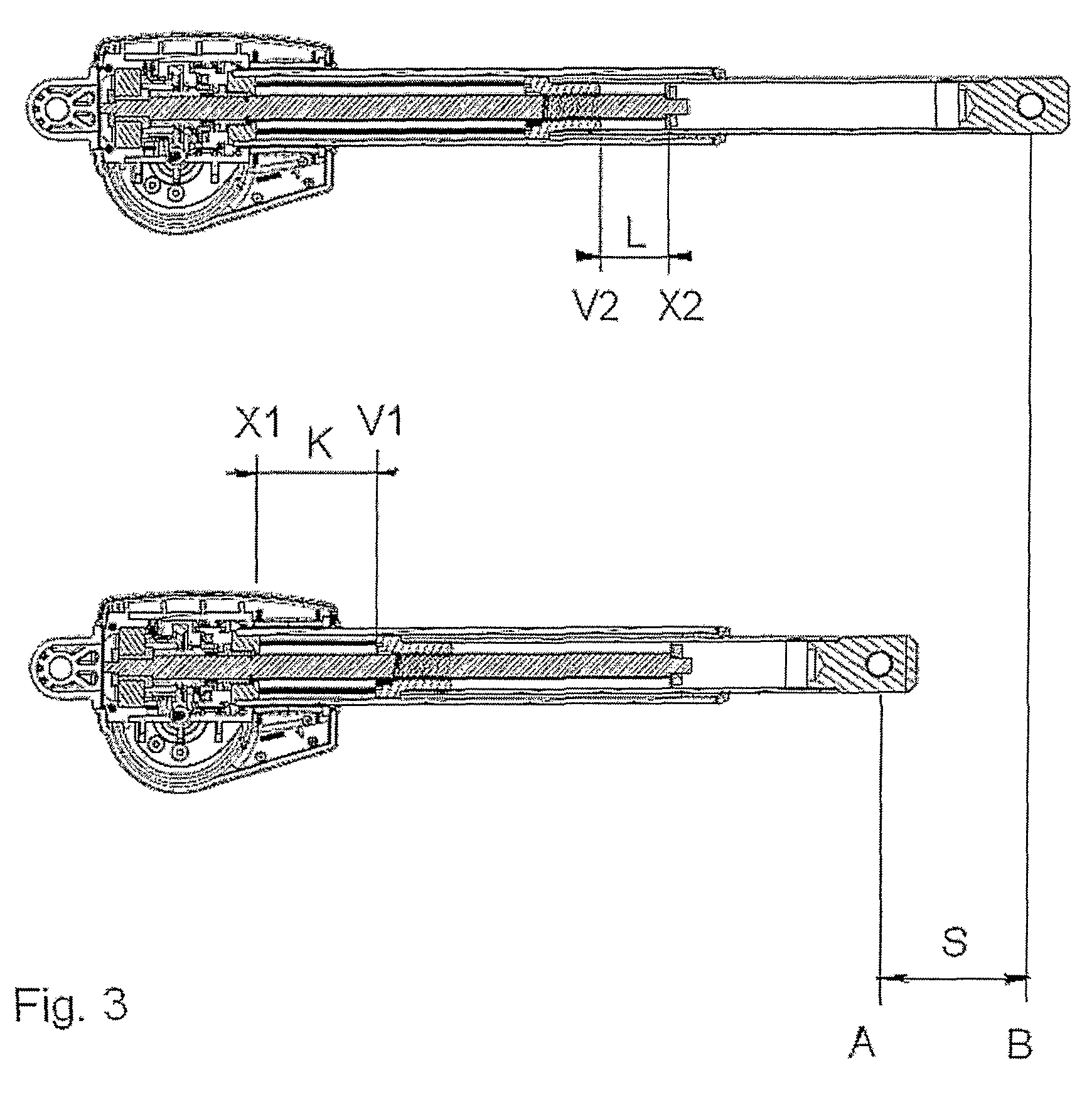
[0028]As it appears from FIG. 1 of the drawings, the main components of the actuator consist of a housing 1, in two parts, with a reversible DC-motor 2, which over a worm drive 3 drives a spindle 4 with a spindle nut 5, to which a tubular activation rod 6 (inner tube) surrounded by an outer tube 7 is secured. The base construction of the actuator is incidentally of the type stated in WO 02 / 29284 and reference to it is incidentally made.

[0029]As can be seen from FIG. 2, a couplings part 8 of the worm wheel is equipped with a magnetic frame yoke 9 with four poles, for determination of the position of the activation rod 6. In this connection two Hall sensors 11, of which only one is visible while the other is hidden under the couplings part 8, are mounted on a small print 10. By rotation of the magnetic frame yoke the Hall sensors are activated when a pole passes by these, and a signal is in that way discharged to a control unit, which via a micro processor calculates the position of t...


PUM


Abstract

A linear actuator includes a spindle nut, where the spindle nut and the spindle between a first and a second point, indicating the length of stroke, can move axially in proportion to each other, depending on whether the spindle or the spindle nut is being driven around via the transmission, and where the position is determined with incremental position sensors, such as at least two Hall sensors or Reed-switches. For determining the position an initiating procedure, where the nut/spindle is moved from a first point on the spindle/nut to a second point on the spindle nut is carried out, and that the number of pulses from the incremental position sensors appearing by it are registered as a measurement for the length of stroke, and the position is subsequently determined in relation to that. It is noted that the control is active before, during and after the operation of the motor. Hereby, absolute position detection is achieved with incremental sensors, where one formerly was obliged to use rotary potentiometers. Simultaneously an optional determination of the length of stroke and its position and immediate possibility to change the same at any time is achieved.

Description

BACKGROUND OF THE INVENTION[0001]1. Field of the Invention[0002]The invention relates to a linear actuator.[0003]2. The Prior Art[0004]The explanation of the invention departs in a linear actuator of the type comprising a linear sliding tubular activation element. A linear actuator comprises an electric motor, which over a transmission drives a spindle. On the spindle is mounted a spindle nut, to which the tubular activation element is secured with its one end. The other end of the tube section is secured with a front fixture to the movable element in the construction, in which the actuator is built in, while the actuator with a rear fixture is secured in the stationary part of the construction or vice versa. During the fastening of the spindle nut, it will either move outwards or inwards on the spindle depending on the direction of rotation, and the tube section thus moves axially outwards or retracts in a manner corresponding to the piston rod on a telescopic cylinder.[0005]Determ...

Claims


Application Information

Patent Timeline
Patent Type & Authority Patents(United States)
IPC IPC(8): H02K41/00
CPCF16H25/2015H02K7/06H02K11/0015H02K11/21H02K7/081
Inventor BASTHOLM, JEPPE
Owner LINAK AS
Why Eureka
Try Eureka