Eureka AIR delivers breakthrough ideas for toughest innovation challenges, trusted by R&D personnel around the world.

Substrate hold apparatus and method for judging substrate push-up state

a substrate and apparatus technology, applied in the direction of apparatus for force/torque/work measurement, force measurement, instruments, etc., can solve the problems of inability to carry out the original specified substrate processing operation during the time, inconvenient substrate, and reduced substrate throughput, etc., to achieve the effect of lowering throughpu

Inactive Publication Date: 2011-10-18
NISSIN ION EQUIP CO LTD
View PDF12 Cites 2 Cited by
  • Summary
  • Abstract
  • Description
  • Claims
  • Application Information

AI Technical Summary

Benefits of technology

[0010]One or more embodiments of the invention to provide an apparatus and a method which not only may carefully check the residual attracting force existing between the electrostatic chuck and substrate to thereby prevent the lowered throughput but also, when the sensor system or substrate is abnormal, may detect the abnormal state of the sensor system or substrate.
[0018]When the position of vicinity of an edge of the substrate is pushed up even if slightly by the push-up member and the substrate is thereby peeled off even if slightly from the electrostatic chuck, the above-mentioned residual attracting force weakens suddenly. Therefore, even if, in the first measurement, the residual attracting force is large and the force measured by the force sensor is larger than the upper limit value, when the force is detected again after waiting for a given time, the residual attracting force may decrease during the time between the first and second measurements and thus the force to be measured using the force sensor may be expected to become equal to or smaller than the upper limit value. When the measured force is equal to or smaller than the upper limit value, it may be judged that the state of the substrate is normal. Therefore, the judgment about the residual attracting force may be made carefully, thereby being able to prevent the lowered throughput.
[0020]The upper limit value and lower limit value used for the judgment in the first measurement may also be referred to as a first upper limit value and a first lower limit value respectively. While the upper limit value and lower limit value used for the judgment in the re-measurement may also be referred to as a second upper limit and a second lower limit value respectively. In this case, the respective upper limit values and lower limit values may be used so as to correspond to actual conditions more properly, which makes it possible to make more accurate judgments.
[0022]According to another aspect of the invention, since the upper and lower limit values used for the judgment to be made in the first measurement are referred to as first upper and lower limit values respectively as well as the upper and lower limit values used for the judgment in the re-measurement are referred to as second upper and lower limit values respectively, the respective upper and lower limit values may be used so as to correspond to actual conditions more properly, thereby being able to make more accurate judgments.

Problems solved by technology

Suppose the residual attracting force is large, when the substrate is removed from the electrostatic chuck, there are caused inconveniences in the substrate, for example, the substrate is caused to bounce, or to be shifted in position, or to be broken.
However, when the processing goes to the residual electric charge removing operation, the originally specified substrate processing operation cannot be carried out during the time.
This raises a problem that the throughput of the substrate (the processing performance of the substrate per unit time) is lowered greatly.
However, when a detecting system (a sensor system) is abnormal or the substrate is abnormal, for example, when a load to be detected originally cannot be detected due to the abnormal state of the detecting system, or when the position of the substrate is shifted greatly on the electrostatic chuck and the load applied to the lift pin is thereby small, the load applied to the lift pin cannot be detected.

Method used


Image

  • Substrate hold apparatus and method for judging substrate push-up state
  • Substrate hold apparatus and method for judging substrate push-up state
  • Substrate hold apparatus and method for judging substrate push-up state

Examples


Embodiment Construction

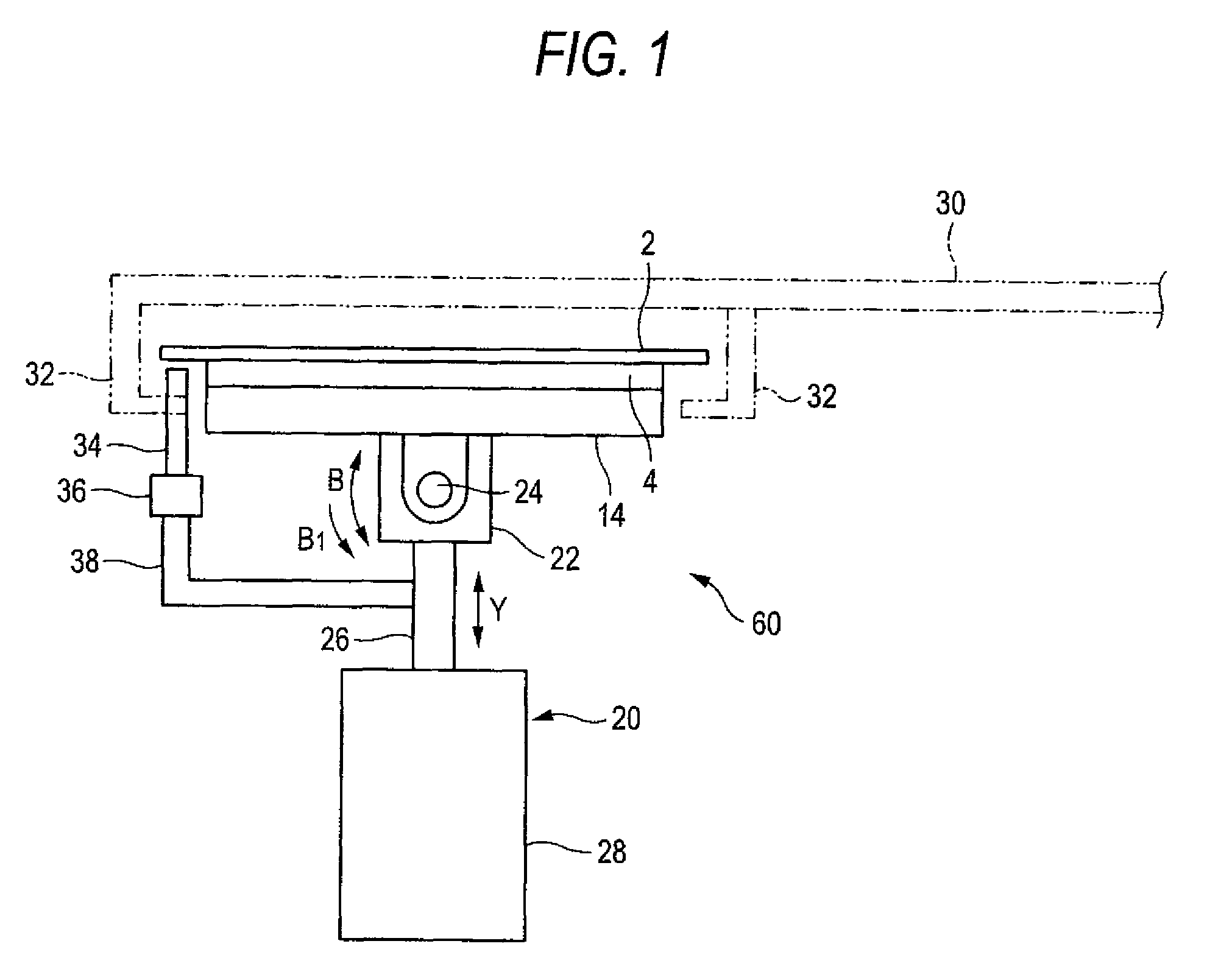
[0035]FIG. 1 is a side view of an embodiment of a mechanism part and a force sensor area of a substrate hold apparatus according to the invention, showing an example of the state thereof just before removal of the substrate is started.

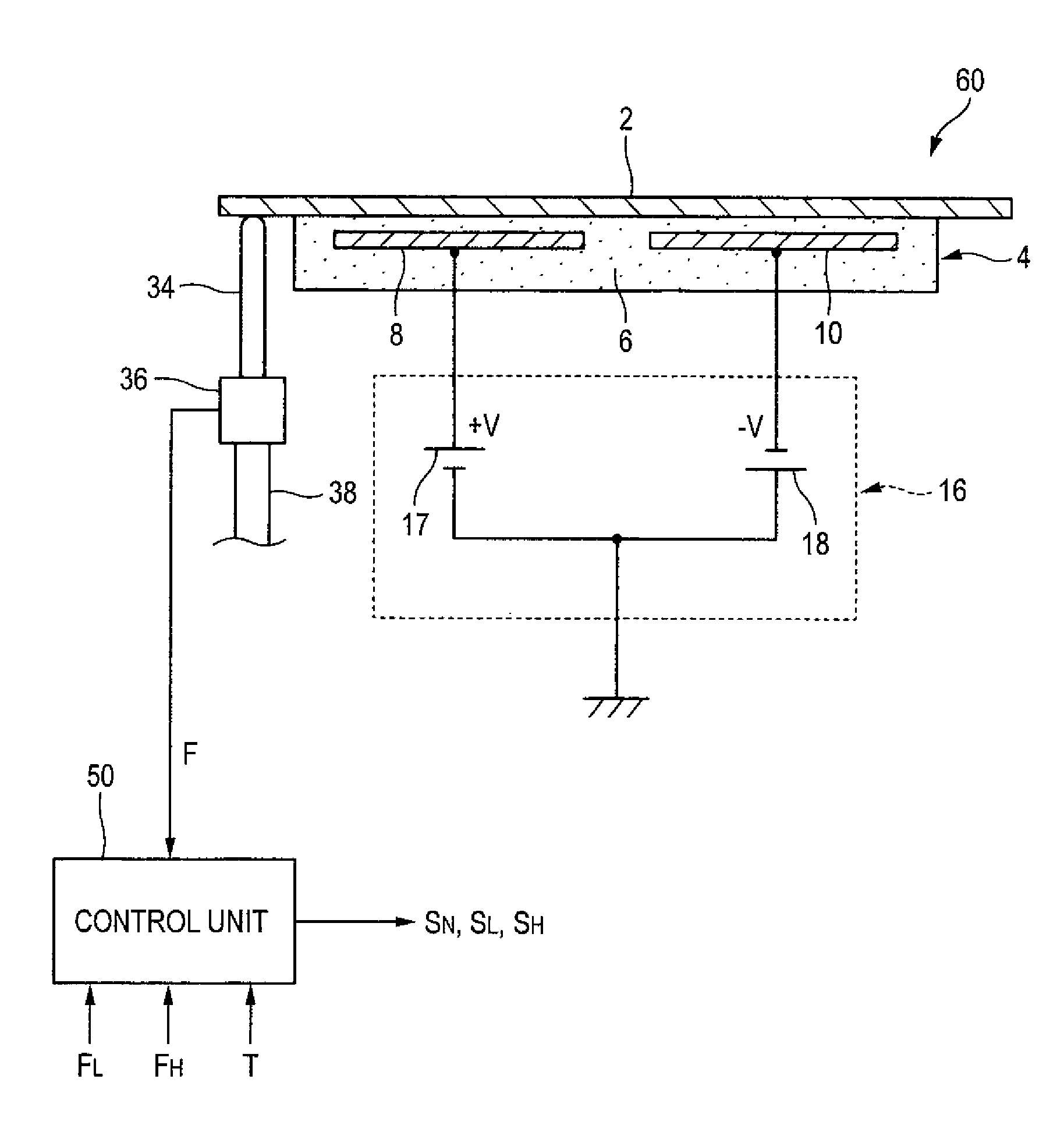
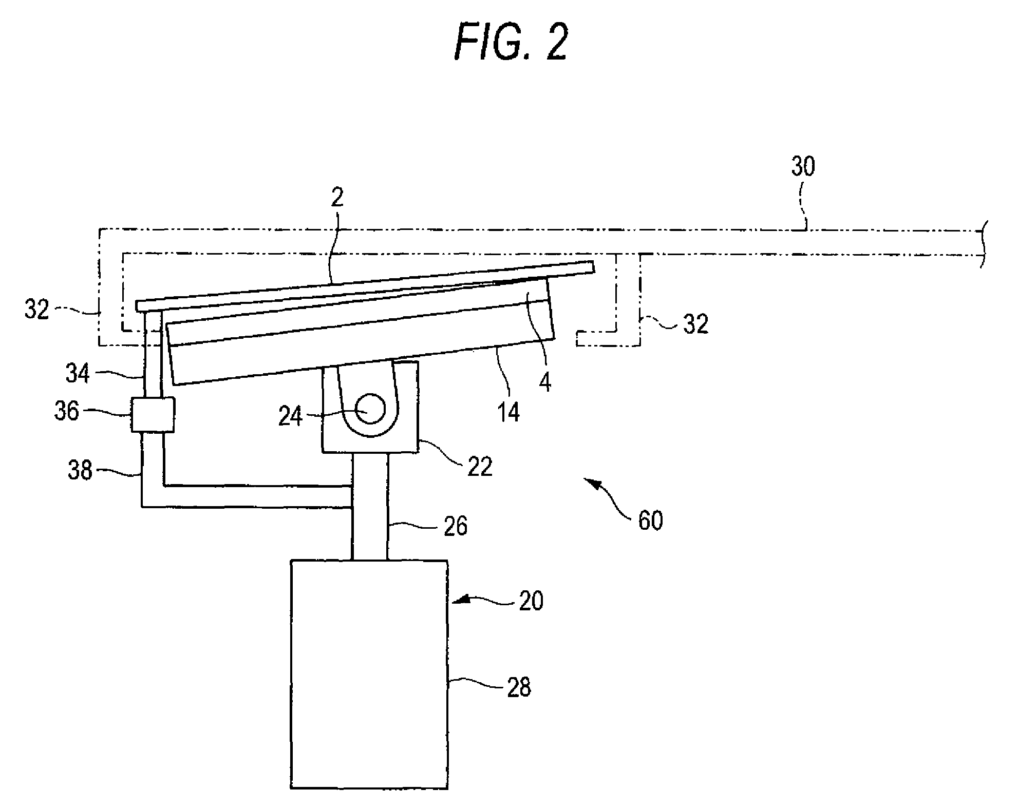
[0036]This substrate hold apparatus 60 includes an electrostatic chuck 4 for electrostatically attracting and holding a substrate (for example, a semiconductor substrate) 2 thereon, a holder 14 for holding the electrostatic chuck, a push-up member 34 contactable with the end (one end) neighboring portion of the substrate 2 on the electrostatic chuck 4 from below for pushing up the substrate 2, and a rotation apparatus 22 serving also as a drive apparatus for driving the electrostatic chuck 4 (in this embodiment, as will be discussed later, inclining the electrostatic chuck 4 slightly) to thereby allow the push-up member 34 to push up the substrate 2.

[0037]And, the substrate hold apparatus 60, as shown in FIG. 5, further includes a force sensor 36 for d...


PUM


Abstract

A substrate hold apparatus is provided an electrostatic chuck for electrostatically attracting and holding a substrate thereon, a push-up member contactable with a position of vicinity of an edge of the substrate on the electrostatic chuck from below for pushing up the substrate, a drive apparatus for driving at least one of the electrostatic chuck and push-up member to thereby allow the push-up member to push up the substrate, a force sensor for detecting a force applied to the push-up member in an pushing-up operation, and a control unit wherein the control unit is configured to measure the force from the force sensor as a first measurement, output a normal state signal when the measured force in the first measurement is equal to or larger than a lower limit value and is equal to or smaller than a upper limit value.

Description

[0001]The present invention claims priority from Japanese Patent Application No. 2007-021021 filed on Jan. 31, 2007, the entire content of which is incorporated herein by reference.BACKGROUND OF INVENTION[0002]1. Field of the Invention[0003]The present invention relates to a substrate hold apparatus which is used in, for example, an ion implantation apparatus, an etching apparatus and a thin film forming apparatus and includes an electrostatic chuck for electrostatically attracting and holding a substrate thereon, and also relates to a method for judging the state of the substrate when it is pushed up using a push-up member after cutting off an applied voltage to the electrostatic chuck.[0004]2. Description of the Related Art[0005]In the below-cited Japanese Patent No. 3814905 (paragraphs 0010-0012, FIGS. 2-5), there is disclosed a substrate hold apparatus which includes an electrostatic chuck for electrostatically attracting and holding a substrate (for example, a semiconductor sub...

Claims


Application Information

Patent Timeline
Patent Type & Authority Patents(United States)
IPC IPC(8): H01L21/683
CPCH01L21/67253H01L21/6831H01L21/68707H02N13/00
Inventor WEIJIANG, ZHAOTAURA, AI
Owner NISSIN ION EQUIP CO LTD
Why Eureka
Eureka Blog
Learn More