Device for eliminating oil particles from the crankcase ventilation gas in an internal combustion engine

a technology of internal combustion engine and ventilation gas, which is applied in the direction of combination devices, filter regeneration, dispersed particle filtration, etc., can solve the problems of affecting the operation exhibiting a relatively low separation effect, and premature wear and tear of the device, so as to prevent the degree of separation, prevent malfunctions, and stable idling of the internal combustion engine

Active Publication Date: 2011-10-25
HENGST WALTER
View PDF12 Cites 19 Cited by
  • Summary
  • Abstract
  • Description
  • Claims
  • Application Information

AI Technical Summary

Benefits of technology

[0017]Preferably provision is further made that the infeed sub-sections run parallel to each other. As a result of this an especially simple geometrical design is obtained, by means of which a simple and cost-effective production is guaranteed. Moreover, in this way all gas partial flows which flow through the infeed sub-sections in the direction of the baffle surface are subject to this same deflection of the flow, so that for each gas partial flow the separation effect is in principle identical.
[0046]In the design of the device with integrated flow control valve the device can be used advantageously for simple and effective crankcase ventilation because the device automatically sets the fresh air flow supplied to the crankcase to operationally optimum quantities.

Problems solved by technology

Therewith this known device is only suitable for applications in which the liquid particles are relatively large.
In the case of this device it is considered disadvantageous that it exhibits a relatively low separation effect with regard to the in particular fine oil droplets carried in the gas flow.
In the case of the design of the device with closing bodies and valve openings that are latticed or shaped like perforated plates there is a risk of valve float, which is unfavorable for the function of the device and which can lead to a premature wear and tear and with it failure of the device.
In addition the precise geometrical correspondence between ribs on the movable element and the passages on the stationary element in practice with limited technical expenditure can only be achieved with difficulty.
Such an arrangement is impaired in its function through deposits and dirt accumulations.
Additionally, to achieve the previously mentioned separation effect for liquid droplets carried in the gas an enlarged installation space is necessary, which in the case of narrow space conditions can lead to accommodation problems.

Method used


Image

  • Device for eliminating oil particles from the crankcase ventilation gas in an internal combustion engine
  • Device for eliminating oil particles from the crankcase ventilation gas in an internal combustion engine
  • Device for eliminating oil particles from the crankcase ventilation gas in an internal combustion engine

Examples


Embodiment Construction

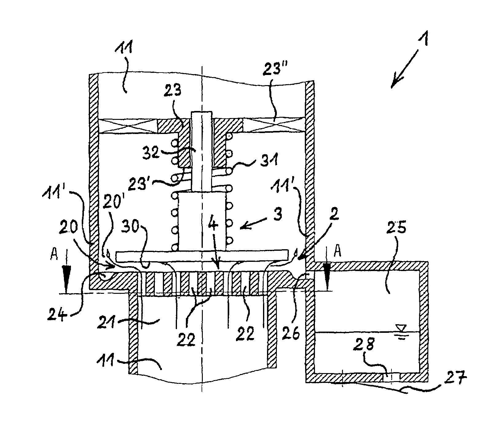
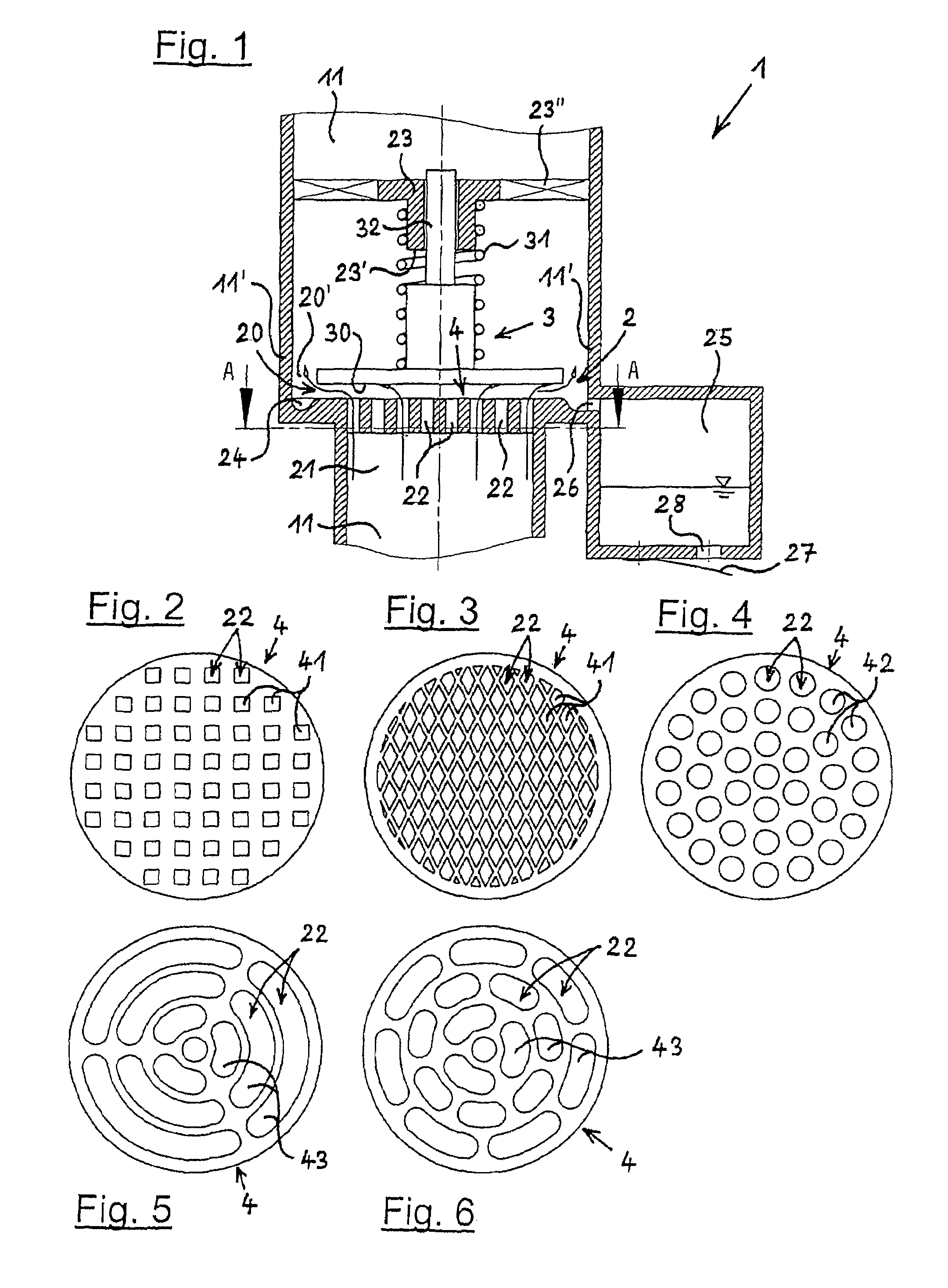
[0063]As FIG. 1 of the drawing shows, the device 1 is arranged in a flow duct 11 for the crankcase ventilation gas of an internal combustion engine, wherein the section of the flow duct 11 visible here has the form of a pipe stepped in diameter. The flow direction of the crankcase ventilation gas runs here from the bottom to the top. In the lower part of the flow duct 11 which is smaller in diameter, a structure 4 is arranged, which sub-divides a previously uniform infeed cross-section 21 into a multitude of infeed sub-sections 22. In the example in accordance with FIG. 1 the infeed sub-sections 22 all run parallel to each other and parallel to the longitudinal direction of the flow ducts 11.

[0064]Downstream from the structure 4, thus above structure 4 here, a baffle surface 30 is provided, which is formed here by the underside of a valve body 3 which is displaceable in axial direction. The valve body 3 possesses a guide section 32 in its upper part averted from the structure 4, sai...


PUM

PropertyMeasurementUnit
widthaaaaaaaaaa
pressureaaaaaaaaaa
right anglesaaaaaaaaaa

Abstract

A device for eliminating oil particles from the crankcase ventilation gas of an internal combustion engine. The device is located in the flow duct of the gas that runs from the crankcase to an induction tract of the engine. The device includes an oil separator in the form of an outlet for the gas with a deflection of the flow, causing the oil particles to be deposited on a baffle surface and thus to be eliminated from the crankcase ventilation gas flow. The device has an infeed cross-section, which lies upstream of the baffle surface when viewed from the flow direction of the crankcase ventilation gas, and which is sub-divided into several infeed sub-sections. The baffle surface is a solid surface that is devoid of perforations. The baffle surface is configured on a valve body, which lies downstream of the infeed sub-sections when viewed in the flow direction of the gas, and which is pre-tensioned by a force. The valve body can be displaced in the opening direction in opposition to the pre-tension, as a result of the differential pressure in the gas between the crankcase and the induction tract.

Description

BACKGROUND OF THE INVENTION[0001]The present invention relates to a device for eliminating oil particles from the crankcase ventilation gas in an internal combustion engine, wherein the device is arranged in the flow duct of the crankcase ventilation gas that runs from the crankcase to an induction tract of the internal combustion machine and wherein the device exhibits an oil separator in the form of an outlet for the crankcase ventilation gas with a deflection of the flow, as a result of which oil particles are deposited on a baffle surface and thus eliminated from the crankcase ventilation flow.[0002]A device for deoiling crankcase ventilation gas in an internal combustion is known from EP 1 285 152 B1, wherein the device exhibits at least one oil separator as well as a bypass duct bypassing the oil separator. In the bypass duct at least one means is provided which opens and closes the bypass duct dependent on a differential pressure. In the process the bypass duct and the means ...

Claims


Application Information

Patent Timeline
Patent Type & Authority Patents(United States)
IPC IPC(8): F02B25/06
CPCB01D45/08F01M13/023F01M13/04F01M2013/0461F01M2013/0488F01M2013/0494
Inventor MEINIG, UWEPIETSCHNER, SIEGHARD
Owner HENGST WALTER
Why Eureka
Try Eureka