Image forming method and apparatus

a technology of image forming and forming method, which is applied in the direction of inking apparatus, coatings, inks, etc., can solve the problems of difficult high-speed printing, inability to form dots of desired shape and size, and interference with the land, so as to achieve accurate patterned lines, short drying time, and high-quality image formation

Active Publication Date: 2011-10-25
FUJIFILM CORP
View PDF18 Cites 52 Cited by
  • Summary
  • Abstract
  • Description
  • Claims
  • Application Information

AI Technical Summary

Benefits of technology

[0034]With the foregoing in view, it is an object of the present invention to provide an image forming method and image forming apparatus that can form a high-quality image in a two-liquid aggregation system using an ink and an aggregation treatment agent, while preventing the deterioration of image quality caused by the movement of coloring material.
[0035]Another object of the present invention is to provide an image forming method and image forming apparatus that can prevent the occurrence of image size reduction caused by aggregation reaction of an ink coloring material in the intermediate transfer system, improve transferability, and form a high-quality image.

Problems solved by technology

However, the problem associated with the inkjet recording system is that where dots are formed to a high density such that the adjacent dots overlap by using ink droplets that are continuously deposited onto the recording medium, the so-called landing interference (bleeding) occurs, namely, the ink droplets forming the adjacent dots merge under the effect of surface tension on the recording medium and dots of desired shape and size cannot be formed.
As a result, where ink droplets are continuously deposited so that the adjacent droplets (dots) overlap on the intermediate transfer body, a problem of bleeding (landing interference) is encountered, namely, the adjacent ink droplets merge on the intermediate transfer body under the effect of surface tension of the droplets and the desired dots cannot be formed.
Such bleeding makes it difficult to perform high-speed printing.
However, the below-described unresolved problems are still associated with image formation in the two-liquid aggregation system and intermediate transfer system, and further improvements are needed.
A new problem that results therefrom is that the output image is greatly distorted with respect to the desired image.
The problems that result from this drawback include image deterioration caused by insufficient amount of coloring material on the recording medium 900 and reverse transfer of the coloring material that has adhered to the absorbing body 910 to the recording medium 900.
(A) Because the coloring material present in the ink is not actively aggregated, where the ink droplets are ejected with a high speed not higher than 10 kHz, the swelling or thickening processes do not proceed in time and landing interference of the adjacent ink droplets occurs.
(B) Because the transferred image formation layer swells due to the absorption of ink solvent, the thickness of the image portion increases causing the so-called “pile height” problem.
Problems arising when the image thickness increases include not only the image quality problem associated with change in appearance of the boundary of the printing zone and non-printing zone, but also a problem associated with that a step is felt when this portion is touched.
The aforementioned problems (B), (C) arise because an image is formed on the recording medium (paper), while the ink solvent is still contained therein.
The problems (A) to (C) cause crucial quality deterioration in high-quality printing.
With the “method using ink aggregation induced by a treatment agent” of section (1), the tests conducted by the inventors demonstrated that when an ink and an aggregating agent react to form an image, shrinking of the image is caused by the ink aggregation reaction and image surface area decreases with respect to the intended one, thereby making it impossible to form a quality image.
The resultant problem is that transferability onto the recording medium is degraded.
Further, the intermediate transfer body has to be cleaned after the transfer, but cleaning ability of the intermediate transfer body surface is degraded by the concavities and convexities.
Therefore, part of the ink layer 934 remains on the intermediate transfer body 930 after the transfer, thereby causing transfer defects such as image deterioration.
The resultant problem is that a thick image is formed on the paper.
For example, when a standard inkjet ink with a pigment concentration in the ink of 4 parts by weight is used, the amount of ink with a thickness about 10 μm is required for high-concentration portions of the image, but when the image on paper has a thickness of 10 μm, a strong unpleasant feel is created by the appearance of the printed matter and problems are associated with quality thereof.

Method used


Image

  • Image forming method and apparatus
  • Image forming method and apparatus
  • Image forming method and apparatus

Examples


first embodiment

[0124]In the first embodiment of the image forming apparatus in accordance with the present invention, an image is directly formed by a two-liquid aggregation method on a recording medium transported by a drum. In this embodiment of the present invention, the explanation will be conduced with respect to a typical inkjet recording apparatus as an image forming apparatus.

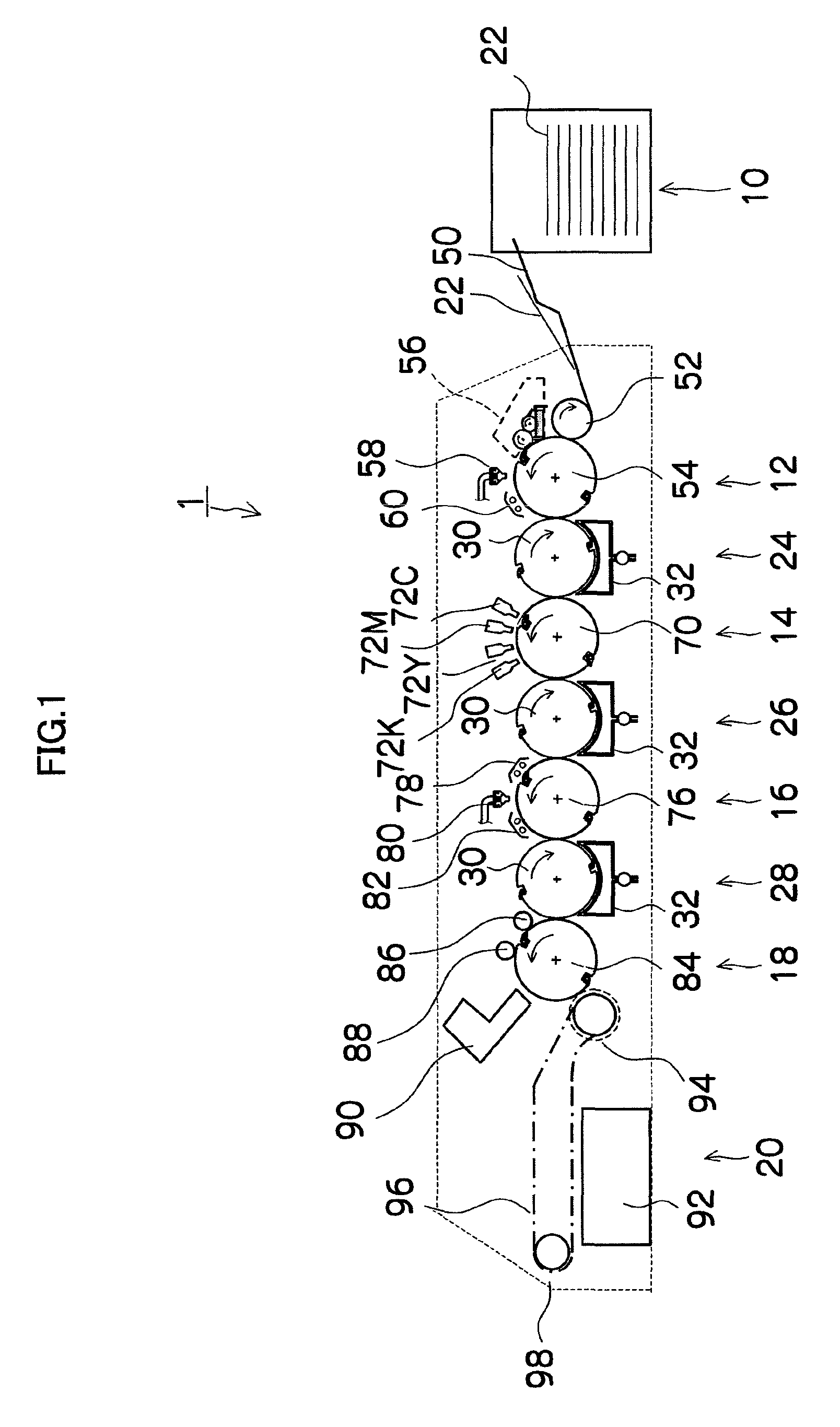
[0125]FIG. 1 is a structural diagram illustrating the entire configuration of an inkjet recording apparatus 1 of the present embodiment. The inkjet recording apparatus 1 shown in the drawing is a device that forms an image on a recording surface of a recording medium 22. The device includes a paper feed unit 10, a treatment liquid application unit 12, an image formation unit 14, a drying unit 16, a fixing unit 18, and a discharge unit 20 as the main components. A recording medium 22 (paper sheets) is stacked in the paper feed unit 10, and the recording medium 22 is fed from the paper feed unit 10 to the treatment liqu...

second embodiment

[0432]In the second embodiment of the image forming apparatus in accordance with the present invention, an intermediate transfer system is employed in which an image is temporarily formed by a two-liquid aggregation method on an intermediate transfer body and this image is then transferred onto a recording medium.

[0433]FIG. 15 is a schematic structural diagram of the inkjet recording apparatus of the second embodiment. An inkjet recording apparatus 200 shown in FIG. 15 employs a two-liquid aggregation system and an intermediate transfer recording system. In this inkjet recording apparatus, an ink image composed of ink aggregates (coloring material aggregates) is formed on an intermediate transfer body 202 by using an ink and an aggregation treatment agent, and the ink image formed on the intermediate transfer body 202 is transferred onto a recording medium 204.

[0434]As shown in FIG. 15, the inkjet recording apparatus 200 of the second embodiment mainly includes an aggregation treatm...

third embodiment

[0486]The third embodiment of the image forming apparatus in accordance with the present invention has a configuration such that in an intermediate transfer system in which an image is temporarily formed by a two-liquid aggregation method on an intermediate transfer body and the image is then transferred onto a recording medium, one treatment liquid including a component causing the coloring material of the ink to aggregate and substantially colorless microparticles is applied to the intermediate transfer body.

[0487]The substantially colorless microparticles used in accordance with the present invention may be any microparticles, provided that they are substantially colorless. The expression “substantially colorless” as used herein refers to a state in which when the microparticles in accordance with the present invention are applied at 0.1 g / m2, the light absorption density in a visible range is not more than 0.1.

[0488]Specific examples of substantially colorless microparticles inc...


PUM

PropertyMeasurementUnit
mean particle sizeaaaaaaaaaa
particle sizeaaaaaaaaaa
thicknessaaaaaaaaaa

Abstract

The image forming method is for forming an image on an image formation body by using an ink liquid including a coloring material and an aggregation treatment agent including a component that causes the coloring material to aggregate. The image forming method includes: an aggregation treatment layer formation step of forming, on the image formation body, a semisolid aggregation treatment layer that includes the aggregation treatment agent and has a moisture content ratio not more than 56%; an ink droplet deposition step of ejecting droplets of the ink liquid and depositing the droplets of the ink liquid onto the image formation body where the aggregation treatment layer has been formed; and a solvent removal step of removing a liquid solvent present on the image formation body after the ink droplet deposition step.

Description

BACKGROUND OF THE INVENTION[0001]1. Field of the Invention[0002]The present invention relates to an image forming method and an image forming apparatus, and more particularly to an image forming method and an image forming apparatus in which an image is formed on an image formation body by using an ink and an aggregation treatment agent.[0003]2. Description of the Related Art[0004]In the inkjet recording system, the recording is performed by discharging ink droplets from nozzles and causing the ink droplets to adhere to a recording medium or the like. By contrast with other systems, noise during the recording operation is low, running cost is low, and image recording with high resolution and high quality can be performed. The ink ejection system can be a piezoelectric system using the displacement of a piezoelectric element or a thermal system using thermal energy generated by a heat-generating element.[0005]Image forming methods in the inkjet recording system generally can be class...

Claims


Application Information

Patent Timeline
Patent Type & Authority Patents(United States)
IPC IPC(8): B41J2/015C09D7/65
CPCB41J2/1606B41J2/2114B41M5/0256C09D7/125C09D7/1275C09D7/1283C09D11/54C09D7/65C09D7/68C09D7/69B41J2/14233B41J2002/012B41J2202/20B41J2202/21B41J11/0015
Inventor CHIWATA, YUHEIYAMANOBE, JUNMAKUTA, TOSHIYUKIKUSUNOKI, NAOKI
Owner FUJIFILM CORP
Why Eureka
Try Eureka