Image monitoring system and object area tracking method

a monitoring system and object technology, applied in closed circuit television systems, instruments, computing, etc., can solve the problems of inability to obtain the correct history of movement of the object area, so as to improve the performance of object tracking and reduce processing load

Inactive Publication Date: 2011-10-25
SONY CORP
View PDF13 Cites 11 Cited by
  • Summary
  • Abstract
  • Description
  • Claims
  • Application Information

AI Technical Summary

Benefits of technology

[0015]It is accordingly desirable to maintain identifying information even when an object area temporarily disappears because the object area is overlapped or hidden, and thereby improve object tracking performance.
[0021]Thus, the identifying information given to the predetermined object area that has disappeared may continue to be retained, and when the predetermined object area reappears, the retained identifying information may be given to the predetermined object area. It is therefore possible to maintain identifying information even when an object area temporarily disappears because the object area is overlapped or hidden, and thereby improve object tracking performance.
[0022]Incidentally, when the predetermined object area disappears as described above, information such for example as a size, position and the like on the predetermined object area when the predetermined object area reappears may be predicted on the basis of the information on the past object area associated with the predetermined object area. Whether the predetermined object area has reappeared may be determined referring to the predicted object area information. It is thus possible to determine the reappearance of the predetermined object area with high accuracy, and improve accuracy in maintenance of identifying numbers.
[0024]Thus, by stopping the retention of identifying information on certain conditions, a need for a process of for example predicting a reappearance position of a predetermined object area, which takes place because the identifying information is retained, is eliminated, so that a processing load can be reduced.
[0025]According to an embodiment of the present invention, in the tracking process associating a current object area with a past object area using common identifying information, identifying information given to a predetermined object area that has disappeared may continue to be retained. When the predetermined object area reappears, the retained identifying information may be given to the predetermined object area. It is therefore possible to maintain the identifying information even when the object area temporarily disappears because the object area is overlapped or hidden, and thereby improve object tracking performance.

Problems solved by technology

In this case, a correct history of movement of the object area may not be obtained.

Method used


Image

  • Image monitoring system and object area tracking method
  • Image monitoring system and object area tracking method
  • Image monitoring system and object area tracking method

Examples


Embodiment Construction

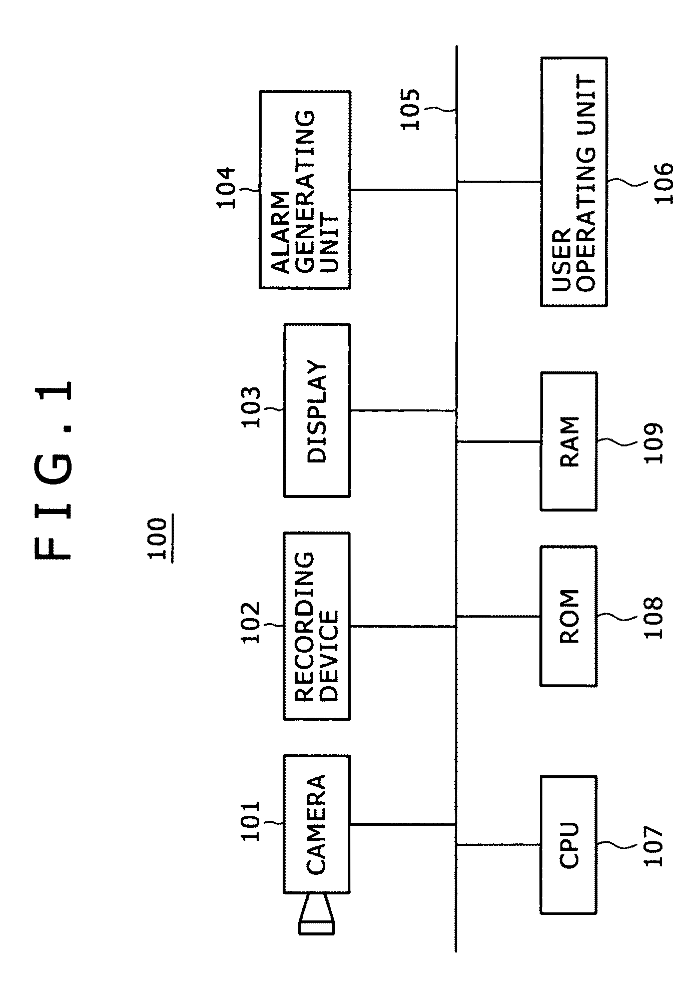
[0037]Preferred embodiments of the present invention will hereinafter be described with reference to the drawings. FIG. 1 shows a configuration of an image monitoring system 100 according to an embodiment. This image monitoring system 100 is formed by connecting each of a camera 101, a recording device 102, a display 103, an alarm generating unit 104, a user operating unit 106, a CPU (Central Processing Unit) 107, a ROM (Read Only Memory) 108, and a RAM (Random Access Memory) 109 to a bus 105.

[0038]The camera 101 is an ITV camera, for example. The recording device 102 stores an image signal obtained by photographing by the camera 101, information on an object area which information is obtained by an object area tracking process in an image processing unit to be described later, and the like. The recording device 102 is formed by for example an HDD (Hard Disk Drive), a semiconductor memory or the like.

[0039]The display 103 displays an image based on an image signal obtained by image ...


PUM


Abstract

An image monitoring system may include an object area detection processing section and an object area tracking processing section. The object area detection processing section may be configured to detect object area information from an image obtained by an input image signal on a basis of the input image signal. The object area tracking processing section may be configured to perform object area tracking processing by associating a current object area with a past object area on a basis of the object area information detected by the object area detection processing section. The object area tracking processing section may associate the current object area with the past object area using unique identifying information. The object area tracking processing section may continue to retain identifying information given to a predetermined object area that has disappeared, and may give the retained identifying information to the predetermined object area when the predetermined object area reappears.

Description

CROSS-REFERENCE TO RELATED APPLICATIONS[0001]This application claims priority to Japanese Patent Application No. JP 2006-165617 filed in the Japanese Patent Office on Jun. 15, 2006, the entire content of which is incorporated herein by reference.BACKGROUND OF THE INVENTION[0002]1. Field of the Invention[0003]The present invention relates to an image monitoring system and an object area tracking method suitable for application to a monitoring system using an ITV camera, for example, and particularly to an image monitoring system and the like that in a tracking process performed by associating a current object area and a past object area with each other using unique identifying information, continue retaining identifying information given to a predetermined object area that has disappeared and give the retained identifying information to the predetermined object area when the predetermined object area reappears. The identifying information can be maintained even when the object area t...

Claims


Application Information

Patent Timeline
Patent Type & Authority Patents(United States)
IPC IPC(8): G06K9/00H04N7/18
CPCH04N7/18
Inventor TSUNASHIMA, NOBUHIRO
Owner SONY CORP
Why Eureka
Try Eureka