Hybrid solar heating system

a solar heating and hybrid technology, applied in the safety of solar heat collectors, lighting and heating equipment, instruments, etc., can solve the problems of serious damage, temperature in the solar heat collector may rise to the point of damage, etc., and achieve the effect of increasing the opacity of the variable opacity layer and reducing the temperature within the interior spa

Inactive Publication Date: 2011-11-01
FLAHERTY B MICHAEL
View PDF53 Cites 13 Cited by
  • Summary
  • Abstract
  • Description
  • Claims
  • Application Information

AI Technical Summary

Benefits of technology

[0011]Preferably, the translucent dome structure includes an inner dome, an outer dome, and a space extending between the inner and outer domes. The transverse hose may include a stiffening structure, such as corrugations, bellows, or a helical structure, that allows the transverse hose to remain round, without collapsing, while being bent sharply.
[0012]In accordance with another aspect of the invention, a solar heat collector is provided with protection from overheating, which might otherwise result in the boiling of a fluid within the solar heat collector. The solar heat collector includes an exterior structure inclosing an interior space, a first tubular structure forming a first fluid path, and a variable opacity layer. The exterior structure includes a translucent portion, with the variable opacity layer extending adjacent to the translucent portion. The opacity of the variable opacity layer is increased in response to an increase in temperature within the interior space and decreased in response to a decrease in temperature within the interior space.

Problems solved by technology

One problem with conventional solar heat collectors arises from the fact that such systems are often used to heat water for household use in climates that are subject to freezing conditions.
When freezing conditions last long enough, particularly at night while heating from solar radiation cannot occur, water within the solar heat collector may freeze, blocking the circulation within the tubing and possibly causing serious damage, such as bursting the tubing due to the expansion.
Since the addition of an antifreeze to the water makes the water unsuitable for domestic use, the water heated within the conventional solar heat collector can only be used as an inlet to a heat exchanger, in which potable water is in turn heated by the solution of antifreeze in water circulating through the solar heat collector.
Another problem with conventional solar heat collectors arises from the fact that, under sunny and warm climatic conditions, particularly when there is little need for the heated fluid produced within the heat collector, temperatures within the solar heat collector may rise to a point at which damage is done, particularly if the fluid within the heat collector is brought to a boil.

Method used


Image

  • Hybrid solar heating system
  • Hybrid solar heating system
  • Hybrid solar heating system

Examples


Embodiment Construction

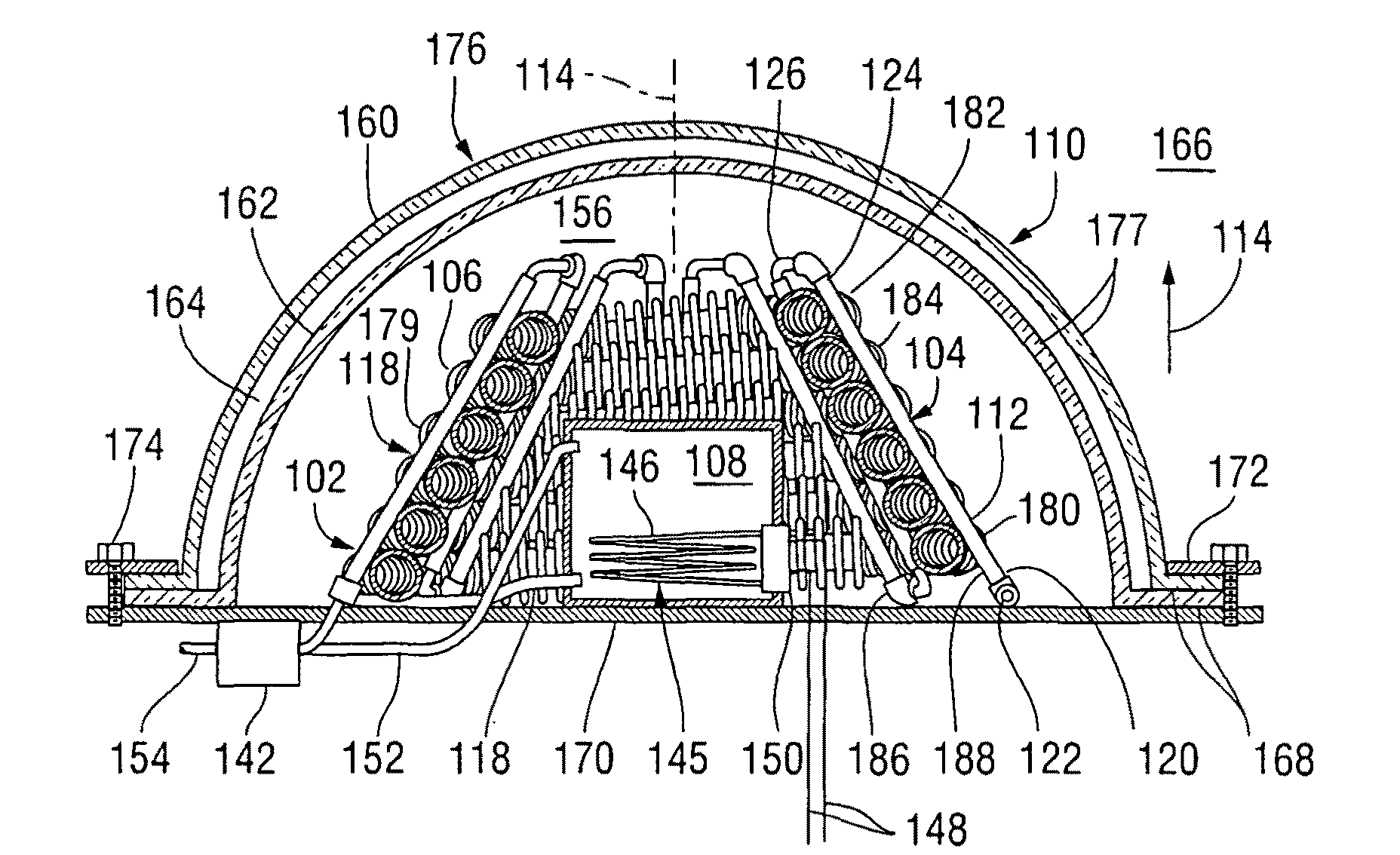
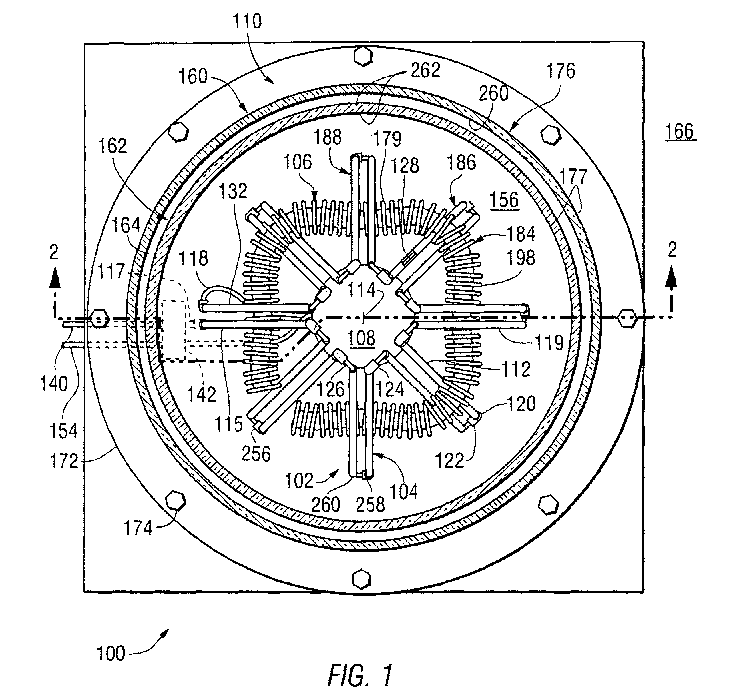
[0031]A hybrid solar heat collector 100 built in accordance with the present invention will first be discussed with reference being made to FIGS. 1 and 2. FIG. 1 is a plan view of the hybrid solar heat collector 100, while FIG. 2 is a cross-sectional elevation thereof, taken as indicated by section lines 2-2 in FIG. 1. The hybrid solar heat collector 100 includes a frame 102 having a plurality of legs 104, a transverse hose 106 winding around the frame 102 and between the legs 104, and a reservoir 108, all held within a translucent dome structure 110.

[0032]Within the frame 102, each of the legs 104 includes a pair of tubes 112, disposed in a circular pattern 113 around a central axis 114 of the hybrid solar heat collector 100 and extending upward, in the direction of arrow 116 and inward, toward the central axis 114. The legs 104 include an inlet / outlet leg 115, in which the tubes 112 are connected to an inlet tube 117 and an intermediate tube 118, and a number of interconnected leg...


PUM


Abstract

A hybrid solar heat collector within a translucent dome structure includes a tubular frame, forming a first fluid path, and a transverse hose winding in a spiral inside and outside alternating legs of the frame to form a second fluid path. The first fluid path is connected to a reservoir in which a heater that is turned on to heat a fluid in the first fluid path when its temperature falls below a threshold. The reservoir is located within the dome structure and is configured to readily heat the space within the dome structure, so that the freezing of fluids within the heat collector is prevented. The translucent dome structure is provided with a layer having an opacity that is increased in response to an increase in temperature above a different threshold level, so that the boiling of fluids within the heat collector is prevented.

Description

RELATED APPLICATIONS[0001]Not ApplicableFEDERALLY SPONSORED RESEARCH OR DEVELOPMENT[0002]Not ApplicableBACKGROUND OF THE INVENTION[0003]1. Field of the Invention[0004]This invention relates to solar heat collecting apparatus, and, more particularly, to solar heat collecting apparatus in which a backup energy source, such as electricity, is used to heat a fluid under conditions of insufficient solar heating, and also in which an opacity of a translucent structure is controlled to prevent overheating of a fluid within the apparatus.[0005]2. Summary of the Background Information[0006]Solar heat collectors generally include translucent walls enclosing tubing in which a fluid, such as water, is circulated to absorb heat from direct sunlight striking the tubing and from the air held within the transparent walls, which is also heated by solar radiation. The solar heat collector may additionally include thermally conductive structures, such as metal fins and plates, which are arranged to ab...

Claims


Application Information

Patent Timeline
Patent Type & Authority Patents(United States)
IPC IPC(8): F24J2/30F24J2/24F24S10/70F24S10/30
CPCF24J2/07F24J2/30F24J2/402F24J2/4623Y02E10/44Y02E10/41F24S40/52F24S50/40F24S20/20F24S10/30Y02E10/40
Inventor FLAHERTY, B. MICHAEL
Owner FLAHERTY B MICHAEL
Why Eureka
Try Eureka