Adjustable power unit mounting attachment for vehicle

a technology for power units and attachments, which is applied in the field of adjustable power units and mounting attachments for vehicles, can solve the problems of affecting the operation of the vehicle, and reinstalling the wheel, so as to facilitate the disassembly and disassembly of the wheel. the effect of the drive wheel

Active Publication Date: 2011-11-01
RAZOR USA
View PDF23 Cites 11 Cited by
  • Summary
  • Abstract
  • Description
  • Claims
  • Application Information

AI Technical Summary

Benefits of technology

[0007]Preferred embodiments of the present powered cycle vehicle are configured to secure the power unit near a desired position on the vehicle while providing favorable and adjustable orientation between portions of the vehicle drive system. Preferred embodiments also are cost-effective to manufacture, thus permitting the system to be employed on lower price-point vehicles.
[0009]Another preferred embodiment is a powered cycle vehicle, the vehicle including a frame, a cycle wheel, a driven wheel, and a mounting bracket. The cycle wheel, having a wheel axle, the wheel axle defining a first axis, the wheel axle rotatably supporting the cycle wheel. The driven wheel operably connected to and in proximity to the cycle wheel, the driven wheel having a driven surface. The mounting bracket affixed to the frame, and the cycle wheel rotatably attached in a locked position to the mounting bracket. The power unit having a motor and a drive wheel, the drive wheel operably connected to the motor and rotatably connected to the driven surface. The power unit slidably positionable on the mounting bracket to allow moving the drive wheel in relation to the rear wheel axis to facilitate disengagement of the drive wheel from the driven surface and removal of the cycle wheel from the mounting bracket.
[0010]Another embodiment is a powered cycle vehicle, the vehicle including a frame, a cycle wheel, a driven wheel, and a power unit. The frame having a first mounting surface and a second mounting surface. The cycle wheel, having a wheel axle, the wheel axle rotatably supporting the cycle wheel and defining a first axis, and the cycle wheel rotatably attached in a locked position to the first mounting surface. The driven wheel operably connected to and in proximity to the cycle wheel, the driven wheel having a driven surface. The power unit having a motor and a drive wheel, the drive wheel operably connected to the motor and rotatably connected to the driven surface. The power unit slidably positionable on the second mounting surface to allow moving the drive wheel in relation to the rear wheel axis to facilitate disengagement of the drive wheel from the driven surface and removal of the cycle wheel from the first mounting surface.

Problems solved by technology

Difficulties presented by various systems include problems related to aligning or maintaining alignment of the motor with the wheel it is coupled to, difficulties in removing the wheel or reinstalling the wheel during maintenance, and creating a system that is small enough, light enough, and inexpensive enough to be suitable for widespread use.
For example, when the motor bracket is attached directly to the wheel, removal, installation, and handling of the wheel during maintenance procedures can be awkward due to the presence of a heavy object pivoting around the axle of the wheel.
Such a system also interferes with accessing the spokes, the hub, and the bearings in cases where these require servicing.
Improper adjustment of the proximity can result in chains or belts falling off, increased resistance, increased wear of parts, and unreliable transmission of drive forces.
Existing electric bicycles or scooters employ mounting arrangements for the motor or other drive unit that are overly complex, difficult to adjust or maintain and expensive to manufacture.

Method used


Image

  • Adjustable power unit mounting attachment for vehicle
  • Adjustable power unit mounting attachment for vehicle
  • Adjustable power unit mounting attachment for vehicle

Examples


Embodiment Construction

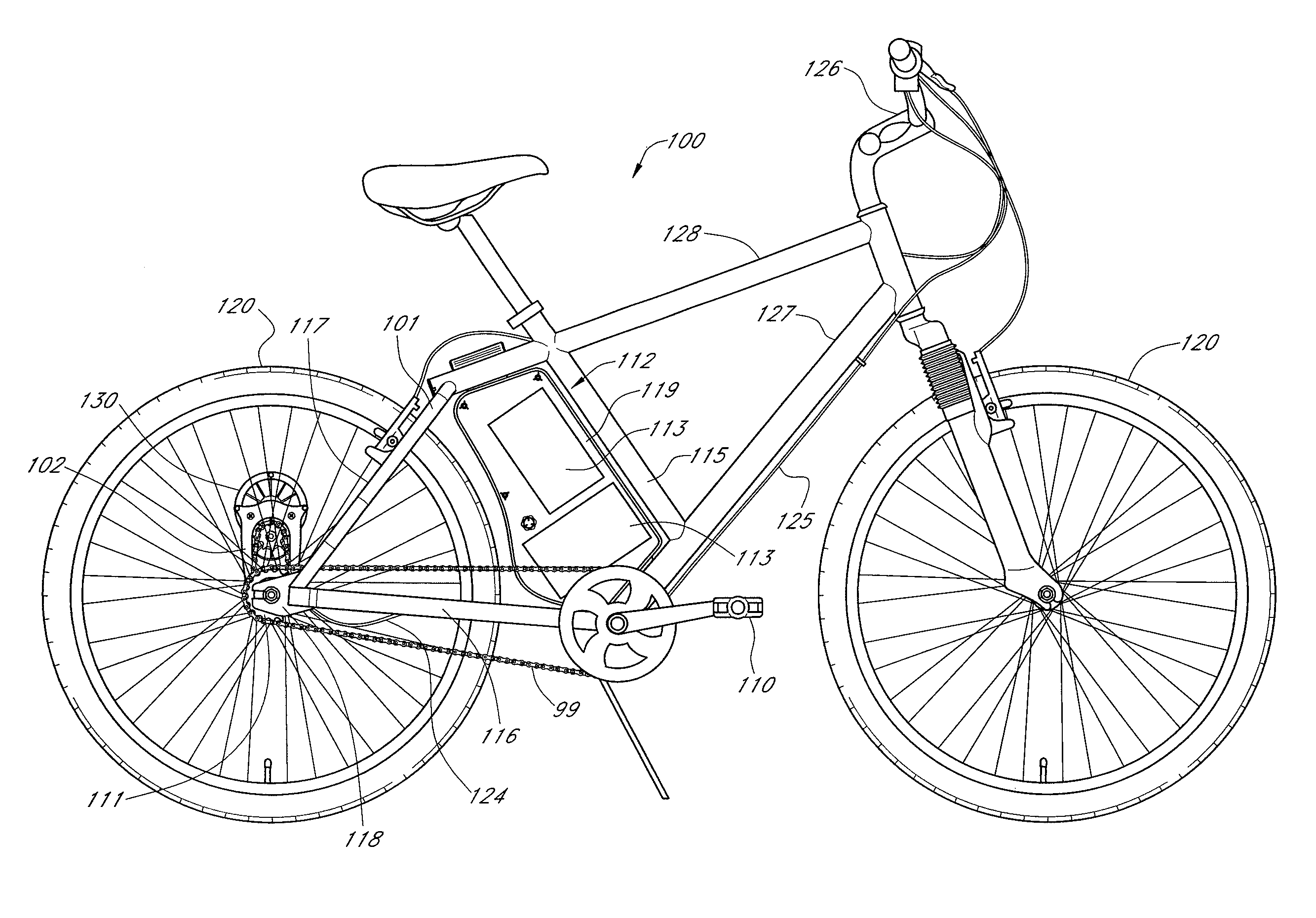
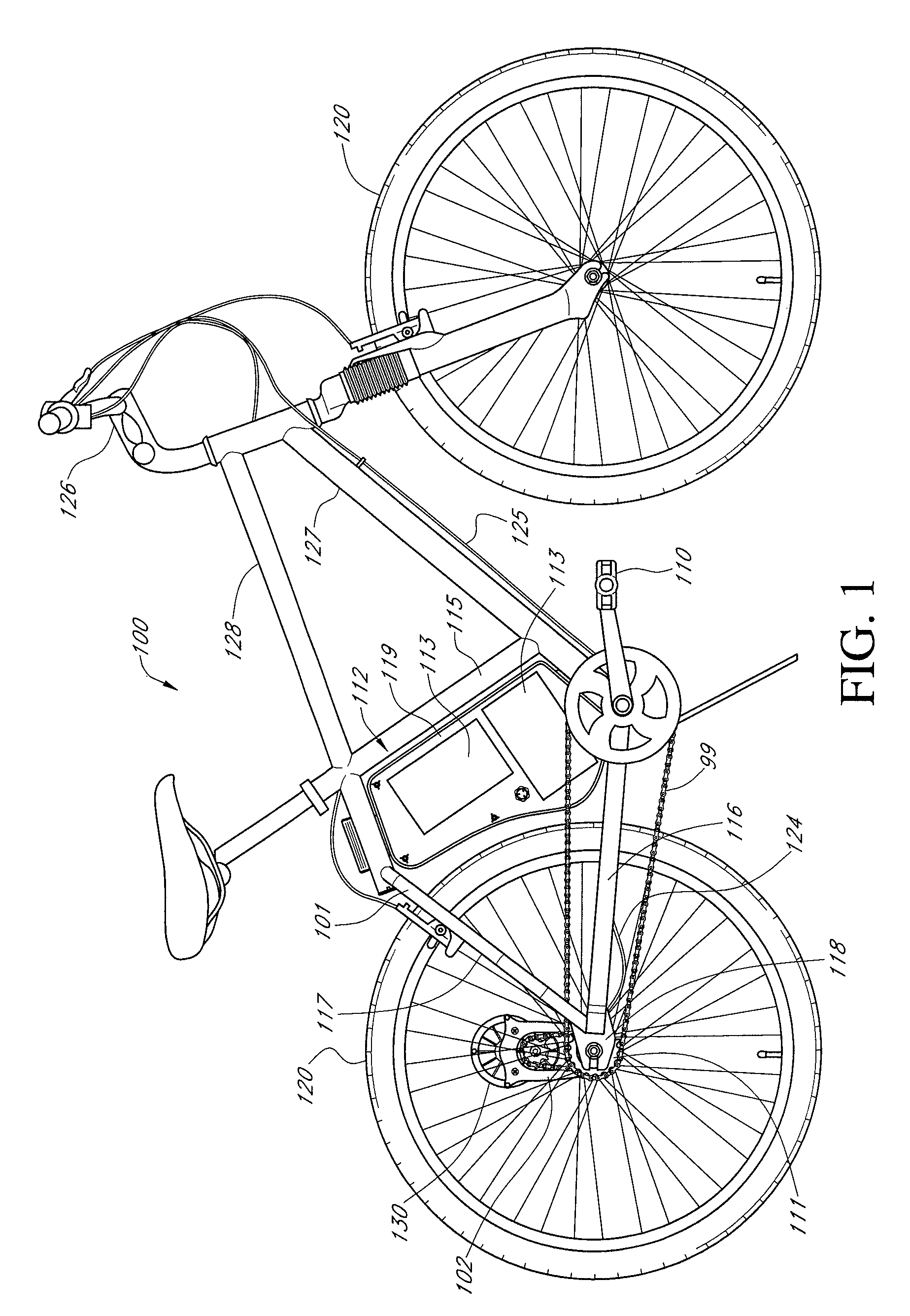
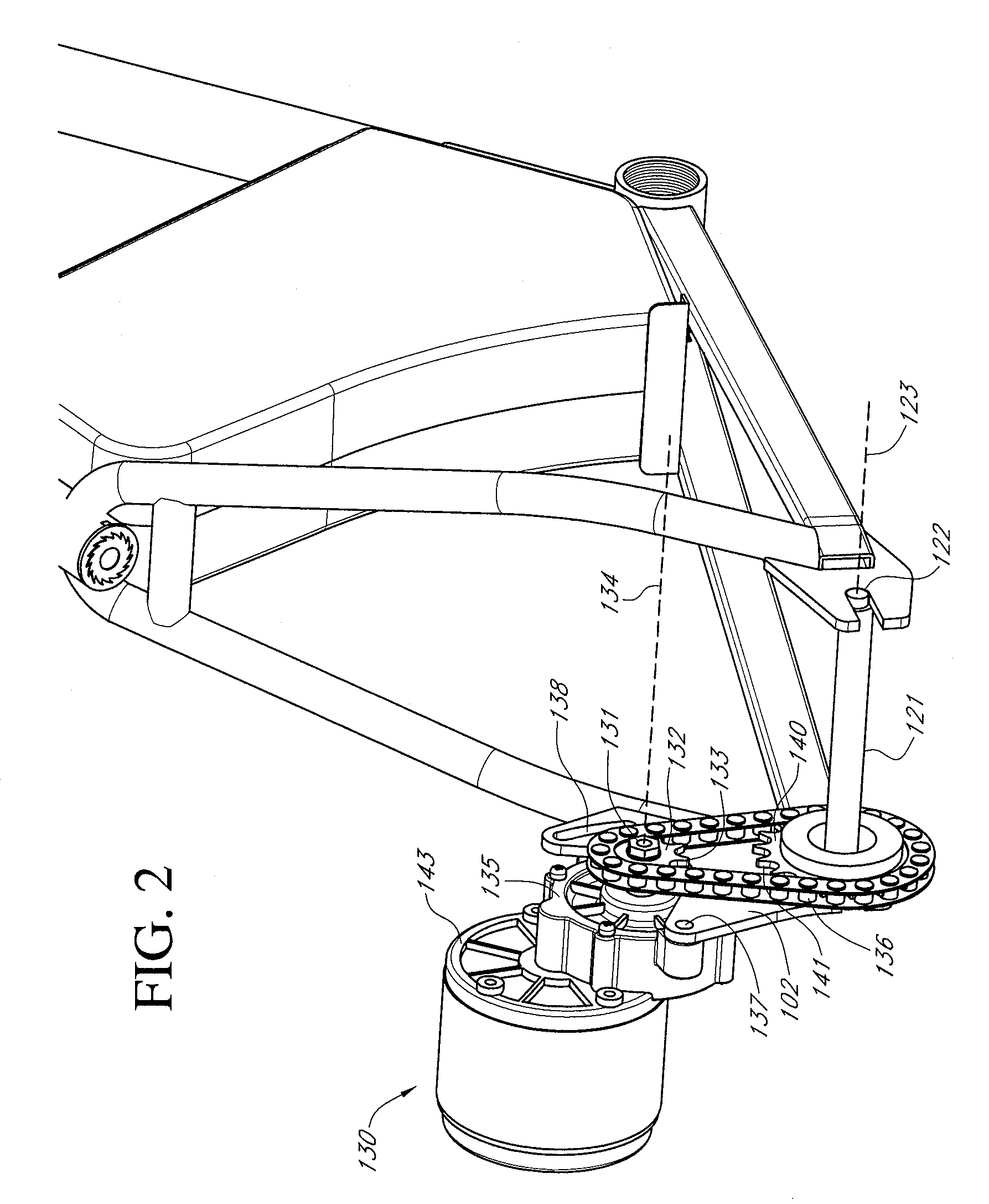
[0018]FIG. 1 illustrates a preferred embodiment of a powered cycle vehicle 100. In the illustrated arrangement, the vehicle is a bicycle including a single front wheel and a single rear wheel. However, the vehicle may be of other types as well, including a scooter, for example, and may include a different number of wheels. The illustrated powered cycle vehicle 100 includes cycle wheels 120, a pedal crank assembly 110 including a drive sprocket, a driven sprocket and one-way clutch (e.g., freewheel) assembly 111, an endless loop (e.g., a belt or a chain) 99 drivingly coupling the pedal crank assembly 110 and the driven sprocket 111, a power unit 130, a power kit 112 with a power source (e.g., one or more batteries) 113, and a seat tube 115. In one embodiment, the power unit 130 includes a drive source (e.g., a motor) 143 attached to a mounting bracket 102, which in turn is attached to the rear portion of the frame 101. Various methods can be used to attach the mounting bracket 102 to...


PUM


Abstract

A powered cycle vehicle having an adjustable mounting system for a power unit is described. A power unit is attached to a wheel mounting bracket which is affixed to the vehicle frame and carries the cycle wheel. The wheel mounting bracket may be a unitary structure that defines a wheel mount location and a power unit mount location. Adjustment of the power unit can be made independently of adjustment of the cycle wheel.

Description

BACKGROUND OF THE INVENTION[0001]1. Field of the Invention[0002]The present invention relates to cycle vehicles, such as scooters or bicycles with two wheels and other related vehicles having more or fewer wheels. More specifically, the present invention relates to powered and / or power-assisted versions of cycle vehicles.[0003]2. Description of the Related Art[0004]Motors, including electric motors, have long been used to power lightweight vehicles such as scooters or bicycles. Various designs have been proposed to couple a motor to the bicycle as well as to transfer the power from the motor to the wheels which contact the ground. Various locations for the motor have been proposed and various attachment schemes. Some have described placing a motor on a rack above the rear wheel, while others have placed a drive unit below the seat and others have attached a motor bracket to the wheel itself. Frequently, the power system will be attached to the existing bicycle frame by clamping the ...

Claims


Application Information

Patent Timeline
Patent Type & Authority Patents(United States)
IPC IPC(8): B62M6/60B62M6/90B62M1/36
CPCB62M6/90B62M6/60B62K25/02
Inventor HADLEY, ROBERT
Owner RAZOR USA
Why Eureka
Try Eureka