Electromotive actuator for deflecting a motor vehicle part

a technology of motor vehicles and actuators, which is applied in the direction of mechanical actuated clutches, interengaging clutches, and gearing, etc., can solve the problems of complex production of this component, low transmission ratio between rotational movement and multi-disk clutches, and high cost. achieve the effect of simple and inexpensive production and increased transmission ratio

Inactive Publication Date: 2011-11-01
ZF FRIEDRICHSHAFEN AG
View PDF18 Cites 7 Cited by
  • Summary
  • Abstract
  • Description
  • Claims
  • Application Information

AI Technical Summary

Benefits of technology

[0010]An object of the present invention is to provide a deflection gear of the above-mentioned type that, with a structure that can be produced simply and inexpensively and that is also compact, has an even further increased transmission ratio.
[0031]In another embodiment, a sealing element is arranged between the threaded nut and the threaded spindle in the area of the ring flange of the threaded nut facing radially towards the outside. This advantageously prevents the penetration of dirt into the screw thread of the threaded nut and of the threaded spindle.
[0032]Moreover, it is felt to be advantageous for the thread of the threaded nut and of the threaded spindle as well as for the thread of the armature nut to be configured so as to be self-locking. This ensures that an adjustment position that has been assumed cannot be changed inadvertently due to the slight forces that are exerted during operation, but rather that the force of the electric motor is necessary for this purpose. Consequently, special components to ensure non-rotatability can be dispensed with in this design.
[0033]Finally, the described electromotive actuator is part of a motor vehicle actuating device, whereby the vehicle part that has been mentioned a number of times is a starting and shifting clutch or its diaphragm spring, a gear brake, a shift track actuator or a gear actuator or a slip coupling of a gear coupling device and / or a gear synchronization device of an automatic transmission or a shifting clutch on a differential gear. The actuator presented here can be constructed to be very small in terms of the actuation forces needed in a given application case, so that it can be used as a very precise adjustment device, also inside the housing of the above-mentioned aggregates or components.

Problems solved by technology

As a consequence, the corresponding operative contours are each limited to a relatively small rotational angle sector of the input element, disadvantageously resulting in a relatively small transmission ratio between the rotational movement and the torque of the input element as well as the axial movement and the axial contact force of each associated output element.
A precise setting of a desired locking power or closing power by means of the axial contact force acting on the appertaining multi-disk clutch is thus hardly possible and moreover, presupposes a considerable absence of play on the transmission path between the electric actuating drive and the input element.
Moreover, there is a need for a very precise manufacture of the cam or ramp surfaces of the input element and output element, as a result of which the production of this component is complicated and hence expensive.

Method used


Image

  • Electromotive actuator for deflecting a motor vehicle part
  • Electromotive actuator for deflecting a motor vehicle part

Examples


Embodiment Construction

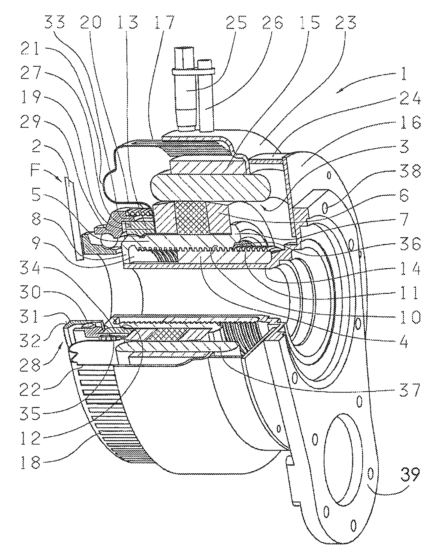
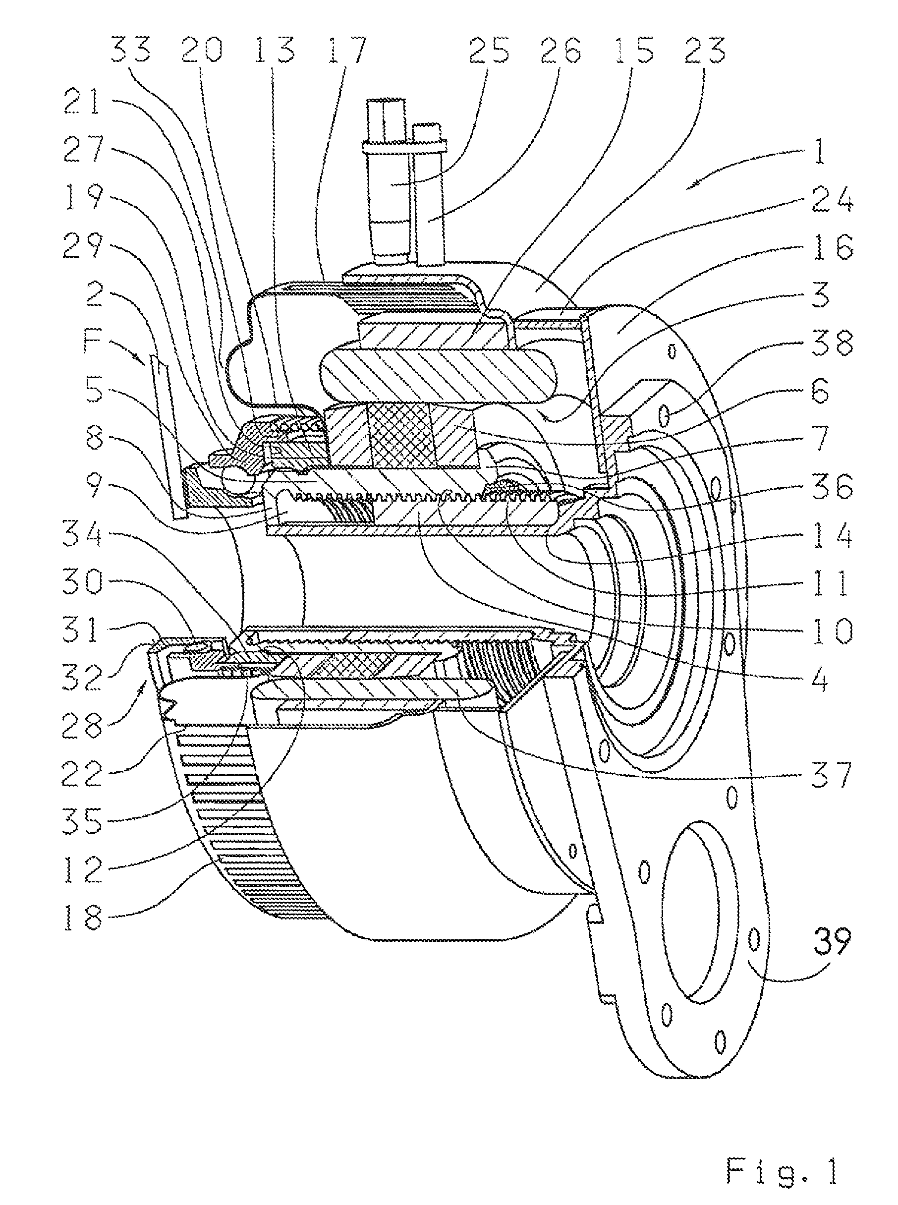
[0035]The single FIGURE shows an electromotive actuator 1 configured according to the invention, in a perspective and cutaway view. The part that is to be actuated in this embodiment is a vehicle component, especially a diaphragm spring 2 of a friction clutch, that is used as starting and shifting clutch in conjunction with an automatic transmission. Here, the actuator 1 is configured as a so-called central clutch release device that opens or closes the friction clutch as a function of control commands of a control device (not shown here) or else that brings it into certain slip operational positions.

[0036]For this purpose, the actuator 1 has an electric motor 3 that can be operated in two rotational directions, as a function of the particular actuation. This electric motor 3 is connected to a deflection gear in the form of a spindle thread-spindle nut arrangement that converts the rotational movement of the electric motor 3 into an axial, linear movement of the control unit of the ...


PUM


Abstract

An electromotive actuator for deflecting a motor vehicle part includes a rotatable component and a non-rotatable component. The rotatable component can be driven by an electric motor in such a way that it can be moved linearly relative to the non-rotatable component between a first position and a second position. In order to create a compact adjustment device, the two components of the actuator are configured respectively as a threaded spindle and a threaded nut, whereby the rotatable component (threaded spindle or threaded nut) is non-rotatably connected to the rotor of the electric motor and can act directly or indirectly on the vehicle part that is to be deflected.

Description

[0001]Priority is claimed to German Patent Application No. DE 10 2006 042 477.8, filed on Sep. 9, 2006, the entire disclosure of which is incorporated by reference herein.[0002]The present invention relates to an electromotive actuator for deflecting a motor vehicle part.BACKGROUND[0003]Modern vehicles contain a relatively large number of electric actuators with which the rotational movement generated by an electric motor that can be actuated by a control device is converted into a linear or rectilinear movement of the vehicle component that is to be moved. A special area of application of such actuators is in the automatic actuation of a starting and shifting clutch of a motor vehicle, whereby the component that is to be actuated can be, for example, a so-called central clutch release device of the friction clutch. During actuation, such a central clutch release device acts, for example, on the diaphragm spring of the clutch in such a way that it is released or brought into a slip ...

Claims


Application Information

Patent Timeline
Patent Type & Authority Patents(United States)
IPC IPC(8): F16D28/00
CPCF16D28/00H02K7/06Y10T74/18664Y10T74/18712
Inventor WEULE, JAN
Owner ZF FRIEDRICHSHAFEN AG
Why Eureka
Try Eureka