
Non-invasive femoral distractor for use in knee surgery

Active Publication Date: 2011-11-01
INNOVATIVE MEDICAL PRODS
View PDF6 Cites 14 Cited by
  • Summary
  • Abstract
  • Description
  • Claims
  • Application Information

AI Technical Summary

Problems solved by technology

The use of such sterile pins, rods, or sterile spreaders and the like to provide insertion requires considerable time and effort to insure insertion in a precise and antiseptic manner within the joint space and thereby create enough space for instruments and implantable devices.

Method used


Image

  • Non-invasive femoral distractor for use in knee surgery
  • Non-invasive femoral distractor for use in knee surgery
  • Non-invasive femoral distractor for use in knee surgery

Examples


Embodiment Construction

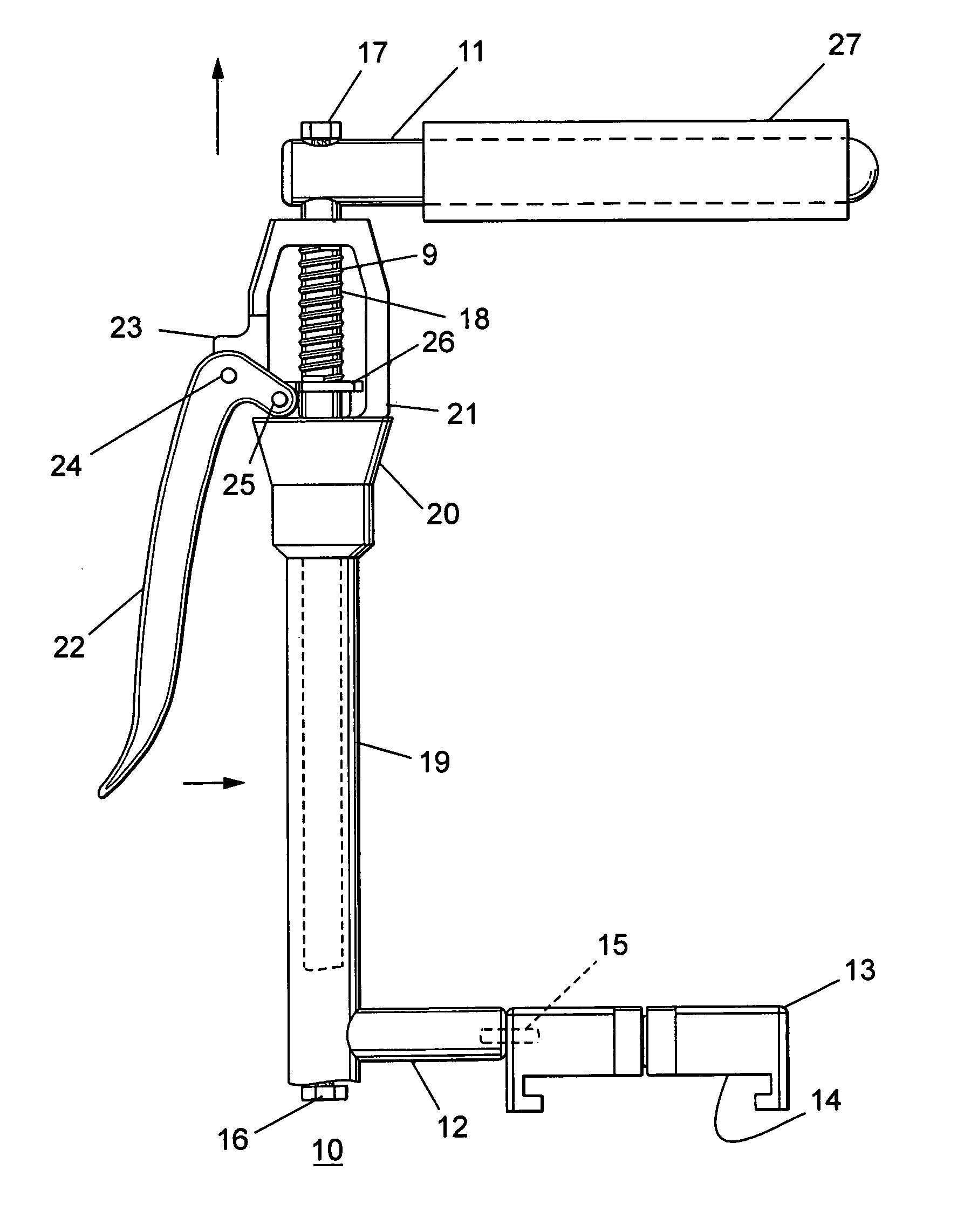
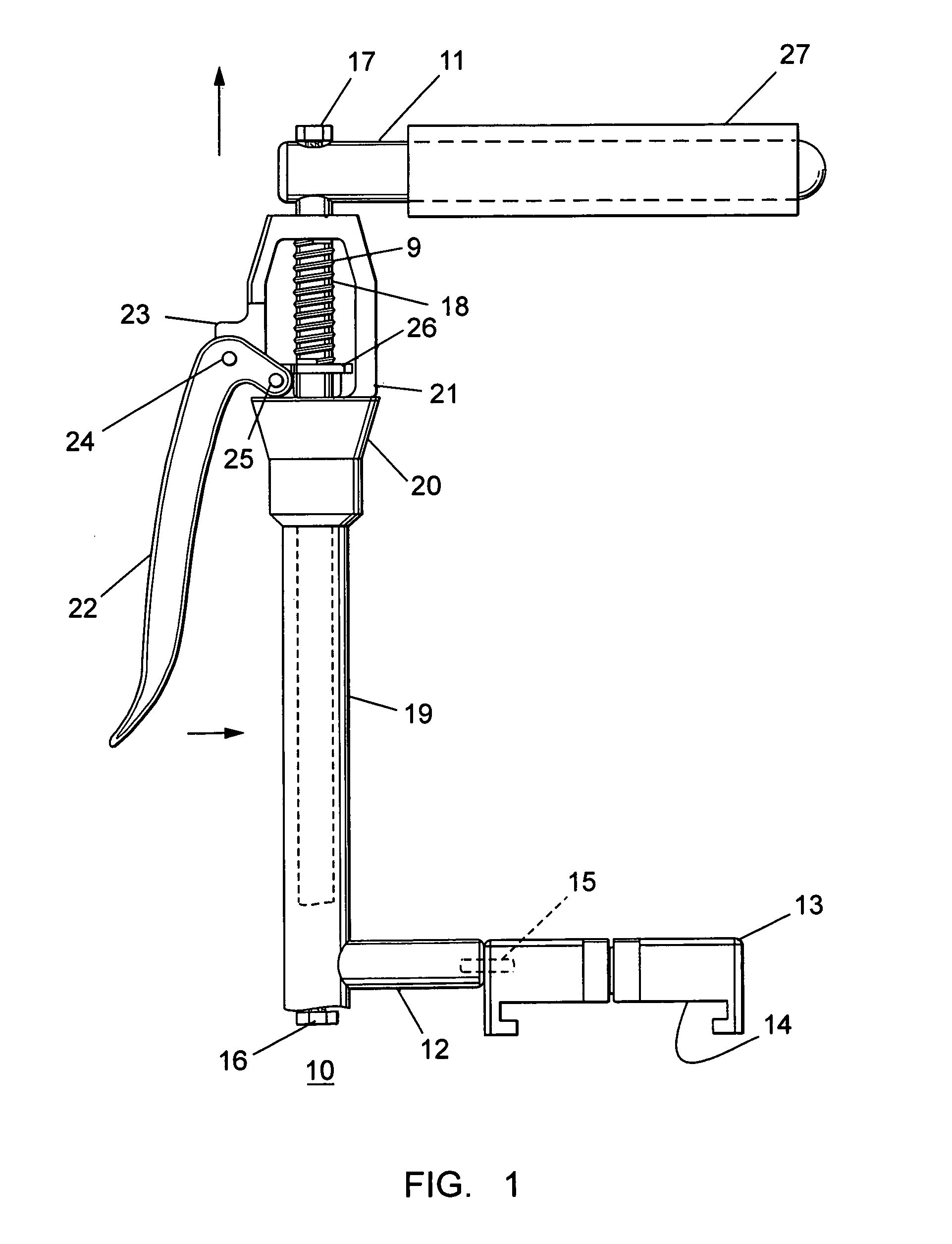
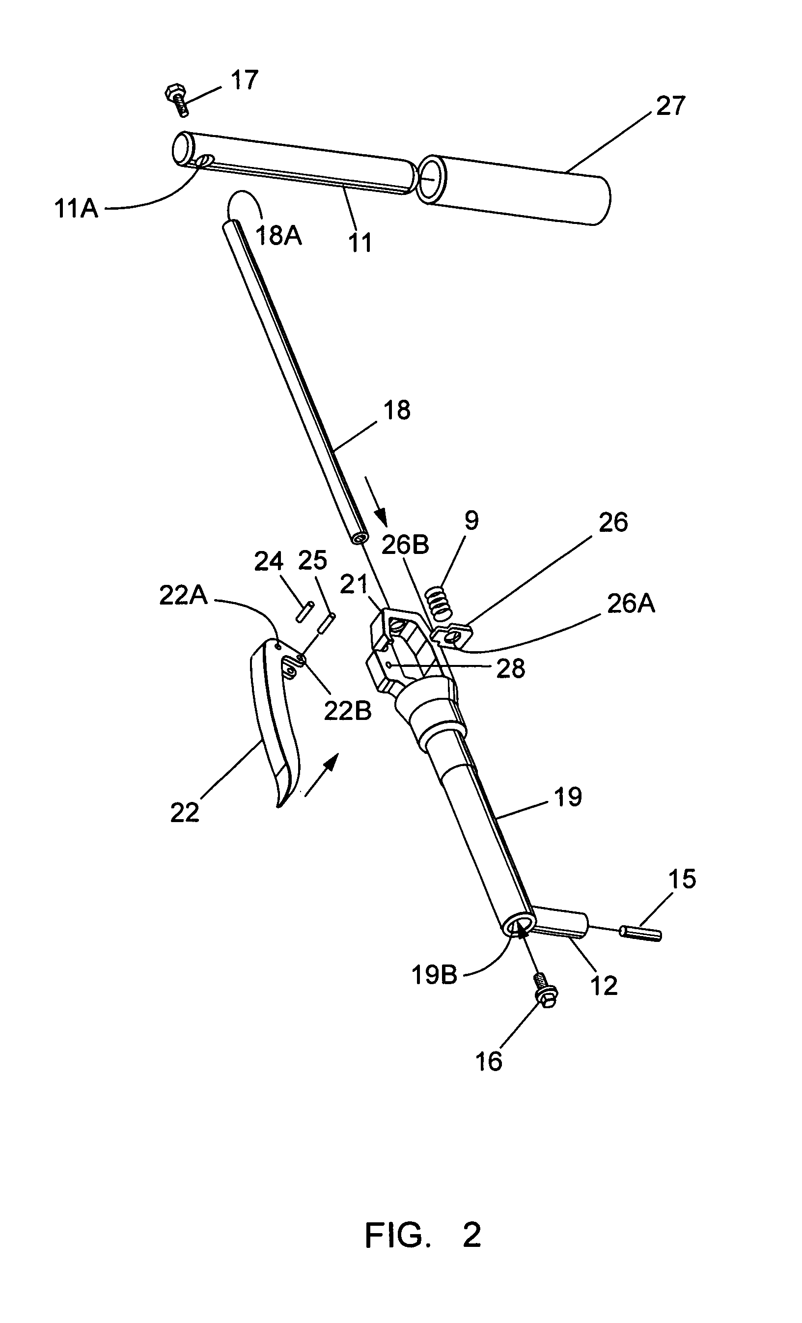
[0008]As shown in FIG. 1, the femoral distractor unit 10 includes a knee support bar 11 at one end for supporting a patient's knee during surgery and a base support bar 12 at the opposite end for attaching to a support base 13, similar to that described within U.S. Pat. No. 7,003,827 entitled “Operating Table Support Clamp”, which patent is incorporated herein for purposes of reference.

[0009]An outer cylinder 19 interconnects between the support bar 11 and support base 13 via the support bar 12 at one end and the U-shaped support 21 at the opposite end thereof. The support bar 12 is attached to the support base 13 via connector pin 15 in press-fit relation to allow the unit 10 to move along the knee positioner carriage rail (not shown) via the extended slot 14.

[0010]Although the unit 10 is arranged herein for attachment to the knee positioner, device, per se, as described in the aforementioned U.S. Pat. No. 7,003,827, for example, it is to be understood that the unit could be direct...


PUM


Abstract

A femoral distractor includes a top post for positioning under a patient's knee and a bottom pin for fixed attachment to a hospital bed rail. A vertical rod extends between the top post and horizontal bottom pin to move the knee joint in the vertical direction upon operation of a trigger assembly.

Description

BACKGROUND OF THE INVENTION[0001]Devices such as described within U.S. Pat. No. 5,116,338 entitled “Apparatus for Knee Prosthesis” and U.S. Pat. No. 5,308,350 entitled “Femoral Distractor for Use in Knee Surgery” are currently available for assisting a surgeon in knee surgery by employing means for insertion within the knee joint to retract or distract the femur from the tibia.[0002]The use of such sterile pins, rods, or sterile spreaders and the like to provide insertion requires considerable time and effort to insure insertion in a precise and antiseptic manner within the joint space and thereby create enough space for instruments and implantable devices.[0003]It would be highly advantageous to be able retract or distract the femur from the tibia during such knee surgery without having to insert any pins, rods, or sterile spreaders into the joint space thereby obscuring vision and occupying instrument space.[0004]On purpose of the instant invention is to describe a simple and effe...

Claims


Application Information

Patent Timeline
IPC IPC(8): A61B17/58A61B17/60A61F2/00
CPCA61B17/025A61B19/203A61B2017/00367A61B2017/0268A61B2019/268A61G13/1245A61G2013/0063A61B90/14A61B2090/571A61G13/0063
Inventor DEMAYO, EDWARD
Owner INNOVATIVE MEDICAL PRODS
Learn More