Centrifugal microfluidic device having sample distribution structure and centrifugal microfluidic system including the centrifugal microfluidic device

a centrifugal microfluidic and microfluidic technology, which is applied in the direction of instruments, separation processes, laboratory glassware, etc., can solve the problems of difficult fluid control operation (e.g., individual driving of valves or fluid distribution)

Active Publication Date: 2011-11-01
PRECISIONBIOSENSOR INC
View PDF14 Cites 14 Cited by
  • Summary
  • Abstract
  • Description
  • Claims
  • Application Information

AI Technical Summary

Benefits of technology

[0009]The present invention provides a centrifugal microfluidic device that can distribute a sample to a plurality of reaction chambers having no vent using one sample moving operation (rotation of the microfluidic device), and a centrifugal microfluidic system including the centrifugal microfluidic device. The centrifugal microfluidic device of the present invention has a simple construction of a microfluidic structure and removes a resistance factor, so that a sample can be rapidly distributed.
[0013]According to an aspect of the present invention, a fluid resistance at inlet channels may be greater than a fluid resistance at the distribution channel. The distribution channel may include a consecutive wave section and connects the non-vented reaction chamber to the consecutive wave section so that a distance between the non-vented reaction chamber to the consecutive wave section is minimized.

Problems solved by technology

However, in this case, a microfluidic structure is not fixed to a rotating frame, compared to the case of a lab-on-a chip where microfluidic structure is fixed to a bottom part.
Additionally, fluid pumping using the centrifugal force is easy, however, an operation for controlling the fluid (e.g., individual driving of a valve or distribution of the fluid) is difficult.

Method used


Image

  • Centrifugal microfluidic device having sample distribution structure and centrifugal microfluidic system including the centrifugal microfluidic device
  • Centrifugal microfluidic device having sample distribution structure and centrifugal microfluidic system including the centrifugal microfluidic device
  • Centrifugal microfluidic device having sample distribution structure and centrifugal microfluidic system including the centrifugal microfluidic device

Examples


Embodiment Construction

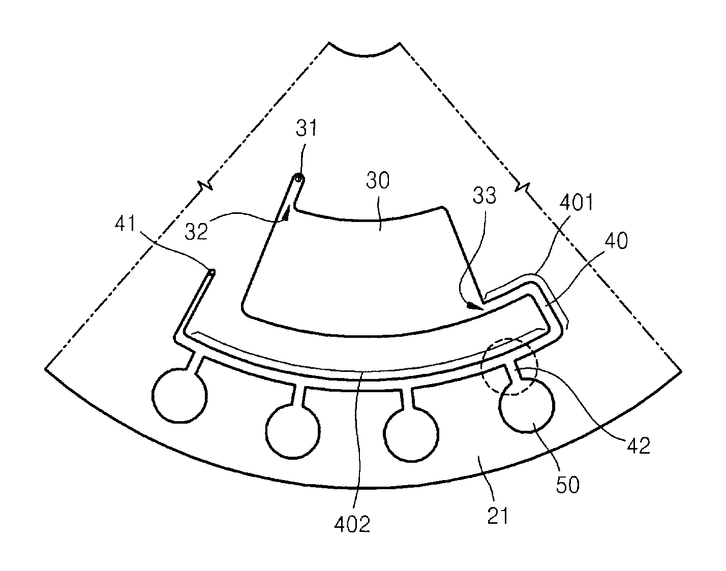
[0030]Hereinafter, the present invention will be described in detail by explaining exemplary embodiments of the invention with reference to the attached drawings. Like reference numerals in the drawings denote like elements. In the drawings, the shapes of illustrated chambers, channels, or the like are simplified, and the sizes of the chambers, channels, or the like are exaggerated for clarity. A sample denotes a material in which a fluid having a living sample (e.g., blood, saliva, or urine) is mixed with a particle having a greater intensity than that of the fluid. In addition, the inside and outside of a platform respectively denote a part that is relatively close to a center of rotation of the platform and a part that is relatively far from the center of rotation of the platform.

[0031]FIG. 1 is a plan view of a centrifugal microfluidic device according to an exemplary embodiment of the present invention. The centrifugal microfluidic device includes a disc-type platform 21 compri...


PUM

PropertyMeasurementUnit
energyaaaaaaaaaa
wavelengthaaaaaaaaaa

Abstract

Provided are a centrifugal microfluidic device having a sample distribution structure and a centrifugal microfluidic system including the centrifugal microfluidic device. The centrifugal microfluidic device includes: a rotatable platform; a sample chamber which is disposed in the rotatable platform and houses a fluid sample; a distribution channel connected to an outlet of the sample chamber; a valve which is disposed in the outlet of the sample chamber; a plurality of non-vented reaction chambers which are disposed in the rotatable platform outside of the distribution channel in the radial direction; and a plurality of inlet channels connecting the distribution channel with the reaction chambers.

Description

CROSS-REFERENCE TO RELATED PATENT APPLICATION[0001]This application claims priority from Korean Patent Application No. 10-2007-0040039, filed on Apr. 24, 2007 in the Korean Intellectual Property Office, the disclosure of which is incorporated herein in its entirety by reference.BACKGROUND OF THE INVENTION[0002]1. Field of the Invention[0003]The present invention relates to a centrifugal microfluidic device and a centrifugal microfluidic system including the centrifugal microfluidic device, and more particularly, to a centrifugal microfluidic device that can distribute a sample to a plurality of non-vented chambers using one moving operation of the sample, and a centrifugal microfluidic system including the centrifugal microfluidic device.[0004]2. Description of the Related Art[0005]Generally, a microfluidic device has a structure including a chamber storing a minute amount of fluid, a channel through which the fluid flows, a valve for controlling the fluid flow, and various function...

Claims


Application Information

Patent Timeline
Patent Type & Authority Patents(United States)
IPC IPC(8): G01N35/00
CPCB01L3/50273B01L3/502738B01L2200/0684B01L2300/0806B01L2300/0861Y10T436/111666B01L2400/06B01L2400/0677G01N21/07Y10T436/25375Y10T436/2575B01L2400/0409B01D17/02G01N37/00B01D25/36C03B37/04
Inventor LEE, BEOM-SEOKCHO, YOON-KYOUNGPARK, JONG-MYEONLEE, JUNG-NAM
Owner PRECISIONBIOSENSOR INC
Why Eureka
Try Eureka