
Method for detecting a fault on a data line

a data line and fault technology, applied in the field of data line fault detection, can solve the problems of high cost, high cost, and different types of errors in data bus of this type, and achieve the effect of simple and cheap circuits, simple and simple circuits

Inactive Publication Date: 2011-11-01
LEAR CORP GMBH
View PDF9 Cites 4 Cited by
  • Summary
  • Abstract
  • Description
  • Claims
  • Application Information

AI Technical Summary

Benefits of technology

Enables simple and cost-effective fault diagnosis in two-wire data buses, allowing for independent evaluation of faults without complex integrated circuits, and can be adapted to various differential data transfer bus systems, providing efficient fault detection and control functions.

Problems solved by technology

Different kinds of errors can occur in data buses of this type.
The circuit is relatively complex and complicated, and thus expensive.
Such interface modules are relatively expensive.

Method used


Image

  • Method for detecting a fault on a data line
  • Method for detecting a fault on a data line

Examples


Embodiment Construction

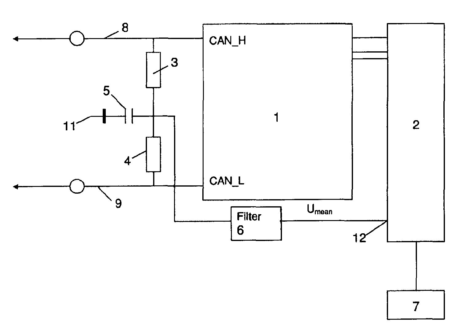
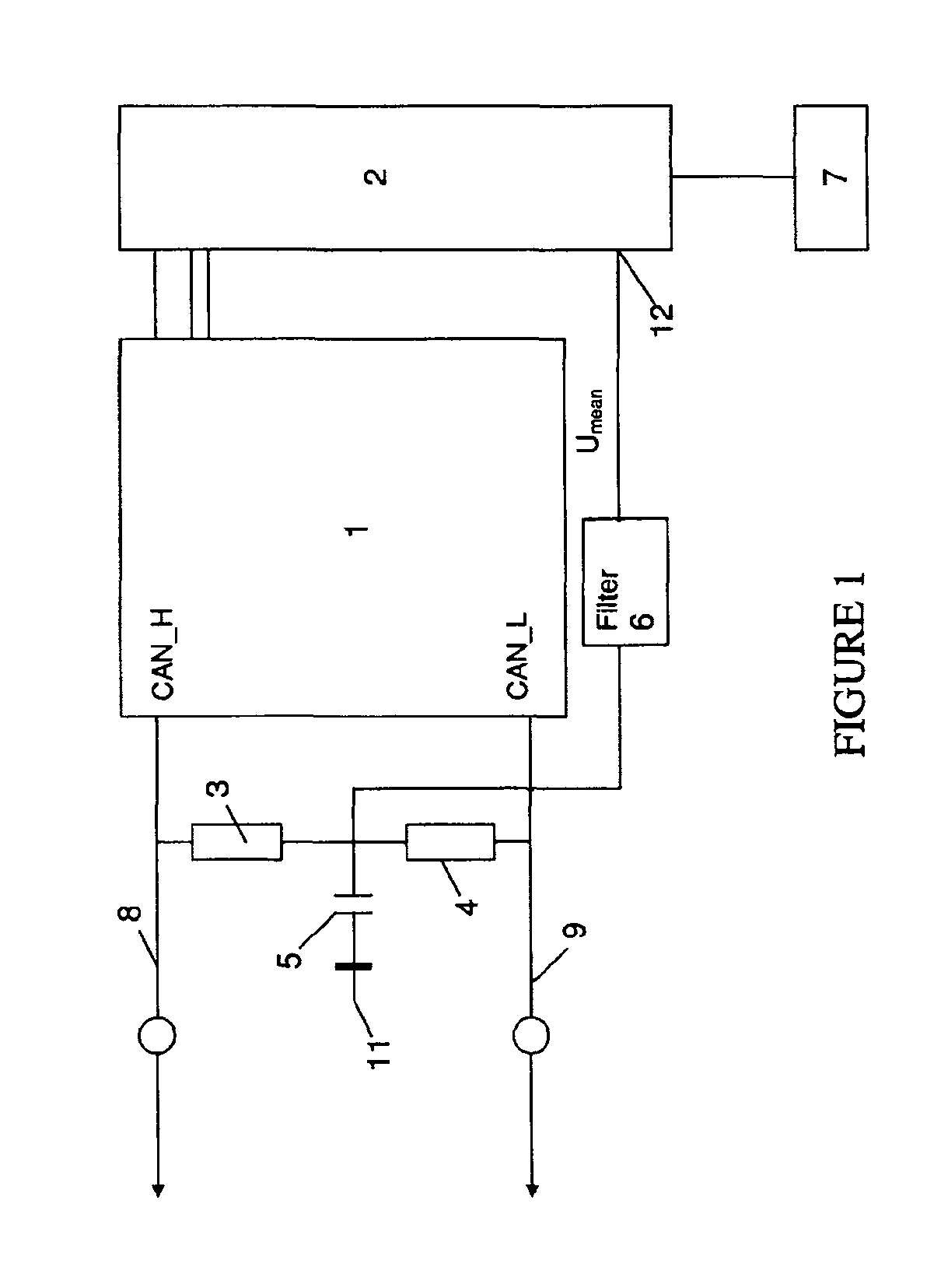
[0023]Multiple embodiments will now be described in detail with the aid of the circuit shown in the single drawing, FIG. 1.

[0024]The circuit depicts an assembly of a CAN-bus system having a two-wire data bus consisting of the data lines 8, 9. The CAN_H-signal is transmitted through the data line 8, and the CAN_L-signal through data line 9, which is generated by the transmitter-receiver unit 1 and the transceiver following control by means of the attached microcontroller 2. The message-related CAN-bus transmits the data on the basis of the CAN-protocol and has two bit states for the bus assignment. The bit state is either recessive or dominant. If a dominant bit is transmitted, then recessive bits sent by the other stations are overwritten. If the identifier of the message is recorded in the identifier list, this message is accepted. The data frame consists of seven CAN-fields.

[0025]Start marks the beginning of a message and synchronizes all stations. The arbitration field produced b...


PUM


Abstract

Multiple embodiments relate to a method for detecting a fault on a data line in a bus system in a two-line data network having at least two control units. A data signal is emitted by a transmitter-receiver unit on the two data lines as a differential voltage signal that includes a defined quiescent current. The data lines are mutually connected through a resistance bridge for detecting the middle voltage. The middle voltage is detected directly by a microcontroller after a low-pass filter or as a digital value after an analog-to-digital conversion. The result is displayed and / or stored. A circuit arrangement for implementing the method is also provided.

Description

CROSS-REFERENCE TO RELATED APPLICATIONS[0001]This application claims foreign priority benefits under 35 U.S.C. §119(a)-(d) to DE 10 2008 002 946.7, filed Jul. 16, 2008, which is hereby incorporated by reference in its entirety.BACKGROUND[0002]1. Technical Field[0003]The multiple embodiments disclosed herein relate to a method for detecting a fault on a data line in a bus system in a two-conductor data network having at least two control units.[0004]2. Background Art[0005]In the case of such two-wire data buses, such as a CAN-Bus (derived from Control Area Network), for which the properties are specified in ISO 11898, individual data bits are transmitted differentially on the two lines of the bus. In a quiescent state, both lines of the bus have about the same potential, since the two lines are coupled to one another through a terminating resistor. A dominant bit is actively transmitted from a transmitter on the bus by enabling a driver current. This transmission occurs differentiall...

Claims


Application Information

Patent Timeline
Patent Type & Authority Patents(United States)
IPC IPC(8): G01R31/08
CPCH04L12/40006H04L2012/40215
Inventor QUECK, MATTHIAS
Owner LEAR CORP GMBH
Features
  • Generate Ideas
  • Intellectual Property
  • Life Sciences
  • Materials
  • Tech Scout
  • Unparalleled Data Quality
  • Higher Quality Content
  • 60% Fewer Hallucinations
Learn More