
Parking assistance device

a technology of assistance device and parking position, which is applied in the direction of pedestrian/occupant safety arrangement, television system, instruments, etc., can solve the problems of large error in the distance from the current position of the self-drive to the target position, and the inability to change the image according to the distance, etc., and achieve good visibility

Active Publication Date: 2011-11-01
AISIN SEIKI KK
View PDF49 Cites 9 Cited by
  • Summary
  • Abstract
  • Description
  • Claims
  • Application Information

AI Technical Summary

Benefits of technology

[0005]The present application was devised in light of the aforementioned problems, and therefore it is an object thereof to provide a parking assistance device for switching between a real image and a converted image at the appropriate position and providing good visibility for the driver.
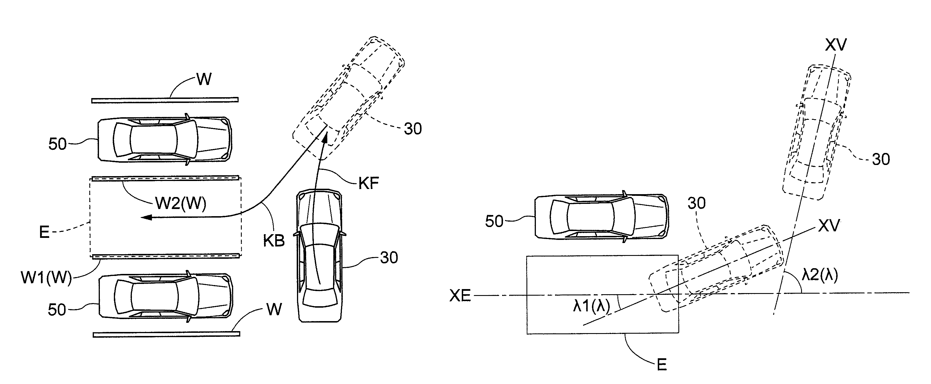
[0007]In parking involving turning, the deflection angle between the vehicle and the parking section is approximately zero at the point when parking is completed. The deflection angle is the current angle of the vehicle relative to the orientation of the vehicle once correctly settled in the parking section. In other words, the deflection angle is the angle made by the axis in the forward and backward direction of the parking section and the axis in the forward and backward direction of the vehicle. The deflection angle becoming equal to or less than the reference deflection angle therefore refers to the driving operation for parking being about to enter the final stage. In the final stage of a driving operation for parking, the scene in the vicinity of the parking section has more utility and value for the driver than the wider scene of the periphery of the vehicle. According to the present characteristic configuration, the image displayed on the display device during final stage of the driving operation for parking is switched from image data to converted image data. Converted image data is image data that has been subjected to image processing, i.e., viewpoint conversion or distortion correction. The image as a whole may contain portions that appear unnatural. However, these unnatural portions are generally on the periphery of the image. When the driving operation for parking is entering the final stage, attention is completely focused on the vicinity of the parking section in the direction of the central axis of the vehicle. The converted image data has good visibility in the central portions of the image, and therefore the image can be displayed so that visibility is improved for the driver overall. As a result, a parking assistance device for switching between a real image and a converted image at the appropriate position and providing good visibility for the driver can be provided.
[0010]Depending on the driver, once the deflection angle has become equal to or less than the reference deflection angle, operations in which the deflection angle exceeds the reference deflection angle are possible, and driving operations in which the vehicle temporarily proceeds forward, and the angle is adjusted are also possible. In these instances, the image data displayed on the display device frequently switches, and visibility is in fact reduced. As mentioned above, the deflection angle becoming equal to or less than the reference deflection angle means that the driving operation for parking is in the final stage. Therefore, once the deflection angle has become equal to or less than the reference deflection angle, the converted image data is displayed on the display device regardless of the deflection angle while a state of parking assistance continues, and good visibility can be maintained.
[0012]In cases where the difference between the image data and the converted image data is large, the driver may be made uncomfortable when the image displayed on the display device switches at the boundary of the reference deflection angle. However, when the image-outputting part described above changes the extent of conversion according to the deflection angle, the feeling of discomfort upon the switch from image data to converted image data is minimized, and visibility can be further improved.
[0014]According to this configuration, the parking section is set on the basis of the image data, and therefore parking assistance can be performed without the driver actively performing the operation for setting the parking section. The parking section is set on the basis of, e.g., the frame lines of the parking space or another parking standard that serves as a reference while parking, and therefore a parking section that is properly matched to the actual parking position can be set. Methods for mechanically setting the parking section on the basis of a constant geometric positional relationship with the vehicle are known, but the error in these methods may be large. In other words, a parking section having displacement of direction and position may be set if the instructions for setting the parking section are not provided while the vehicle is in the proper orientation according to the parking assistance device. However, according to the present characteristic configuration, a parking section that is well-matched to the actual parking position can be set. As a result, convenience for the driver is enhanced, and a parking assistance device allowing good visibility can be provided.
[0016]Once the driving operation for parking enters the final stage, the vehicle itself is present in the parking section, and therefore the portion of the parking section contained in the image data decreases. Verifying the degree of parallel alignment with the parking section therefore becomes progressively more difficult. However, according to the configuration above, extension lines of the parking section are laid over the converted image data and displayed on the display device. Good visibility can therefore be maintained even near the completion of the driving operation.

Problems solved by technology

However, in the case of a parking assistance device in which the target position is not set, the image cannot be switched according the distance from the current position of the self vehicle to the target position.
In parking assistance devices in which a rough parking target, e.g., only the frame of the parking space, is set, the target position cannot be accurately defined, and the error in the distance from the current position of the self vehicle to the target position is large.
Turning is involved in many parking situations, and large errors are therefore possible when calculating the distance to the target position even when the target position is defined.
As a result, the image cannot be switched at the appropriate position, and visibility may be impaired.
However, these unnatural portions are generally on the periphery of the image.

Method used


Image

  • Parking assistance device
  • Parking assistance device
  • Parking assistance device

Examples


Embodiment Construction

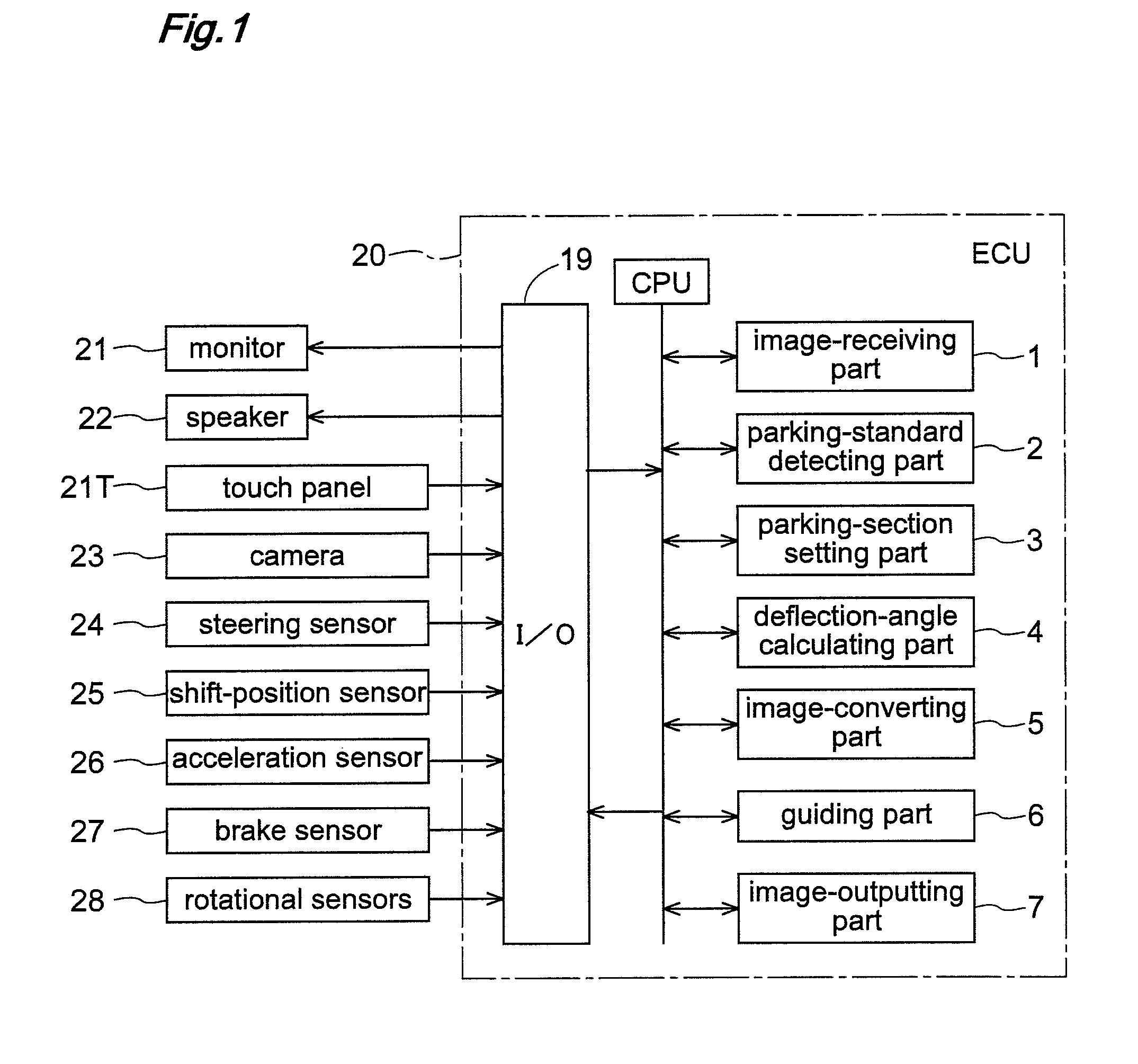
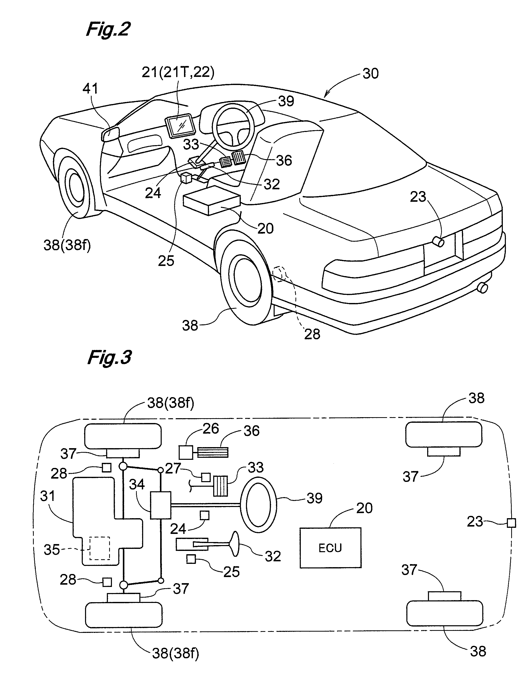
[0032]Embodiments of the present invention will be described below on the basis of the drawings. FIG. 1 is a block diagram that schematically shows an sample configuration of the parking assistance device of the present invention; FIG. 2 is a perspective view that shows an example of a vehicle 30 provided with the parking assistance device of the embodiment; and FIG. 3 is a block diagram that schematically shows an example configuration of the vehicle 30.

[0033]The parking assistance device of the present invention comprises an ECU 20 as the central core. The ECU 20 is provided with an input-output interface 19 for inputting and outputting information, and a microprocessor or DSP (digital signal processor) for processing the information obtained from the input-output interface 19. It shall be apparent that part or all of the input-output interface 19 may be contained in such a processor. The ECU 20 comprises electrical circuits for which the processor is the central core component. T...


PUM


Abstract

An imaging device mounted on a vehicle (30) acquires image data resulting from capturing an image of a scene around the vehicle (30). A parking section (E) corresponding to the desired parking position is set. The image data is subjected to an image-converting process that includes at least one of viewpoint conversion and distortion correction. A deflection angle (λ) between the vehicle (30) and the parking section (E) is calculated. The image data is outputted until the deflection angle (λ) becomes equal to or less than a predetermined reference deflection angle, the image data being outputted to a display adapted for installation in the vehicle (30). Once the deflection angle (λ) has become equal to or less than the reference deflection angle, converted image data that has been subjected to the image-converting process is outputted.

Description

TECHNICAL FIELD[0001]The present invention relates to a parking assistance device for assisting a driving operation involving turning for parking a vehicle in a desired parking position.BACKGROUND ART[0002]In recent years, awareness of safety while driving vehicles has improved, and a variety of technologies for facilitating the driving operations or the like and thereby improving safety have been proposed and put into practice. Parking assistance devices have been implemented in which, e.g., locations that are difficult for the driver to see are imaged by a camera mounted on the vehicle and are displayed on a monitor device within the vehicle cabin. A device for monitoring the rear of a vehicle, in which an actual image of the rear of a self vehicle captured by a camera is shown on a display, is disclosed in Patent Document 1, the reference for which is given below. This device switches the displayed image from an actual image to a converted image as the distance from the current p...

Claims


Application Information

Patent Timeline
Patent Type & Authority Patents(United States)
IPC IPC(8): H04N7/00H04N7/18
CPCG06K9/00812G06T1/0007B62D15/0275B60W30/06G06V20/586B60R1/00B60R21/00
Inventor KUBOYAMA, TSUYOSHIWATANABE, KAZUYA
Owner AISIN SEIKI KK
Learn More