Locking differential

a technology of locking differential and cam tooth, which is applied in the field of differentials, can solve the problems of less than ideal interaction between cam tooth and clutch drive teeth, relatively mechanically complex locking differential types of the type commonly known in the art, and increase the cost of manufacturing devices, so as to reduce the number of hold out rings, reduce the number of internal wear, and reduce the effect of internal wear

Active Publication Date: 2011-11-08
EATON INTELLIGENT POWER LTD
View PDF8 Cites 4 Cited by
  • Summary
  • Abstract
  • Description
  • Claims
  • Application Information

AI Technical Summary

Benefits of technology

[0010]Because the cam assembly includes a pair of cam members that have teeth specially designed to interact with each other to provide a corresponding camming action thereby moving the clutch members axially away from the central driver, this arrangement results in less internal wear in the locking differential mechanism as well as quieter and smoother operation. The locking differential also has a reduced number of hold out rings when compared to the devices known in the related art. Thus, the present invention is mechanically efficient and may be manufactured at a reduced cost.

Problems solved by technology

For example, locking differentials of the type commonly known in the art are relatively mechanically complex and this complexity adds to the cost of manufacturing the devices.
In addition, the interaction between the cam teeth and a portion of the driven teeth on the clutch is less than ideal because the driven teeth function to transmit torque from the central driver as well as respond to speed differentials to ride up the surfaces of the cam teeth.
This results in the creation of noise and vibration during conditions when there is a speed differential between the axle half shafts.

Method used


Image

  • Locking differential
  • Locking differential
  • Locking differential

Examples


Embodiment Construction

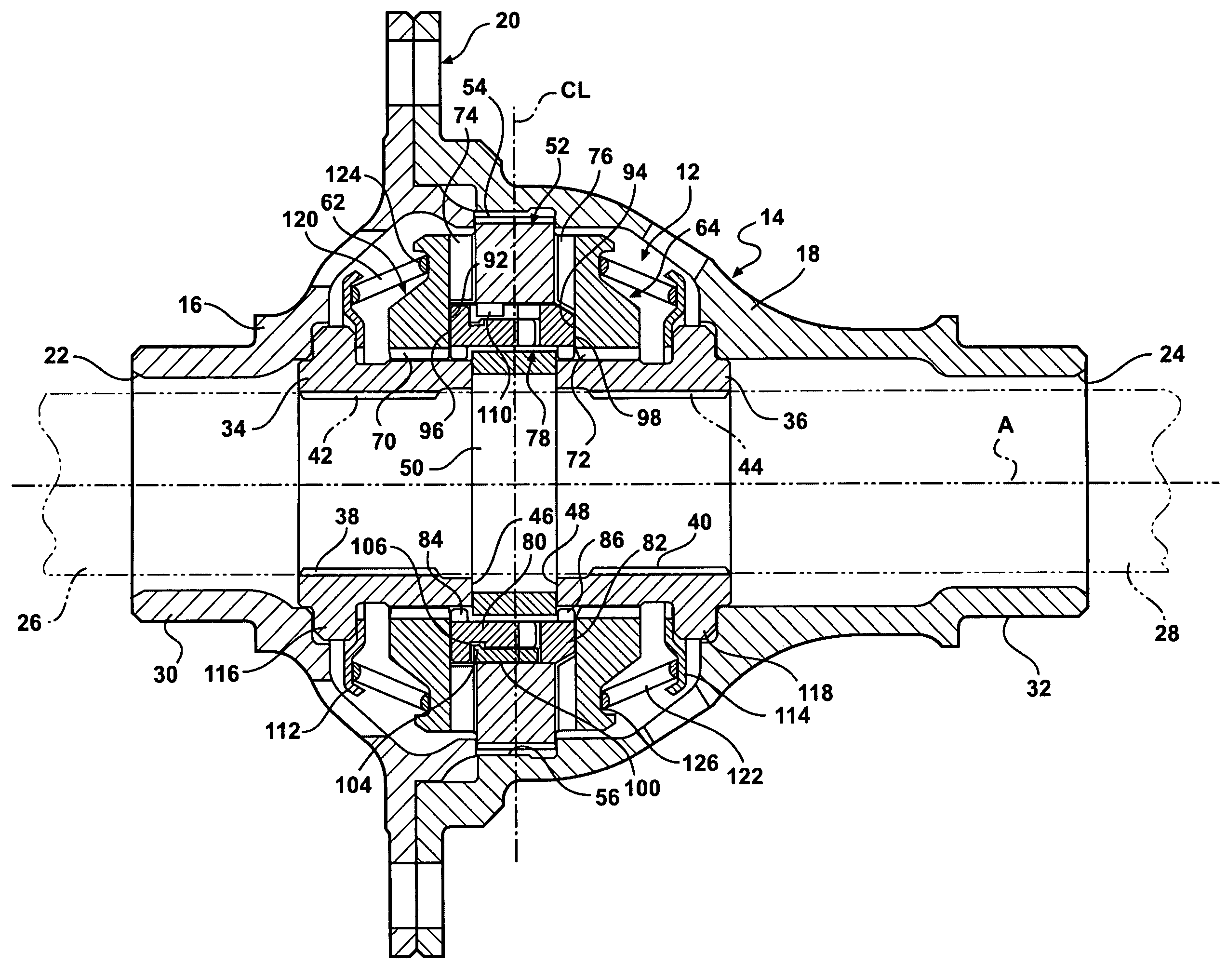
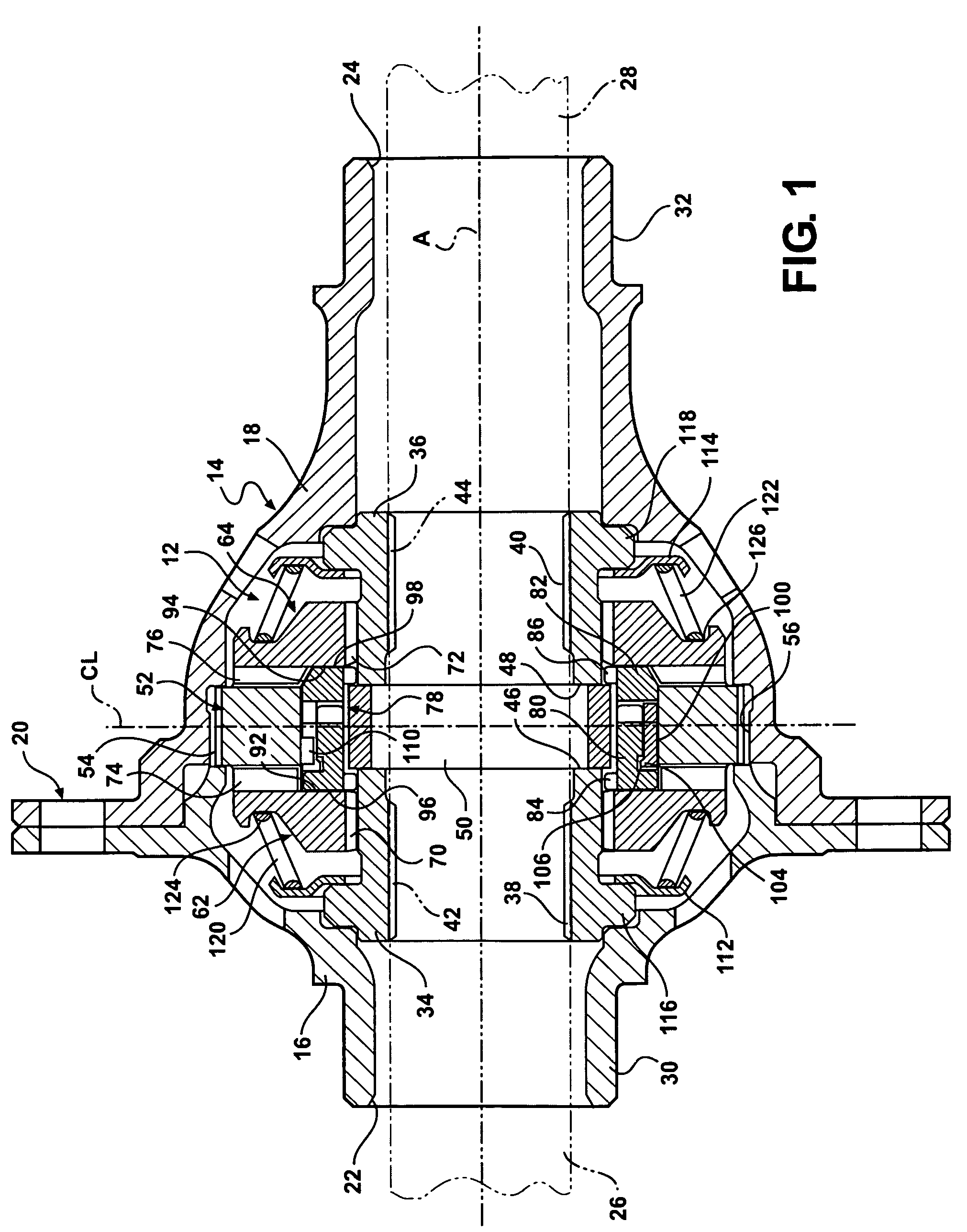
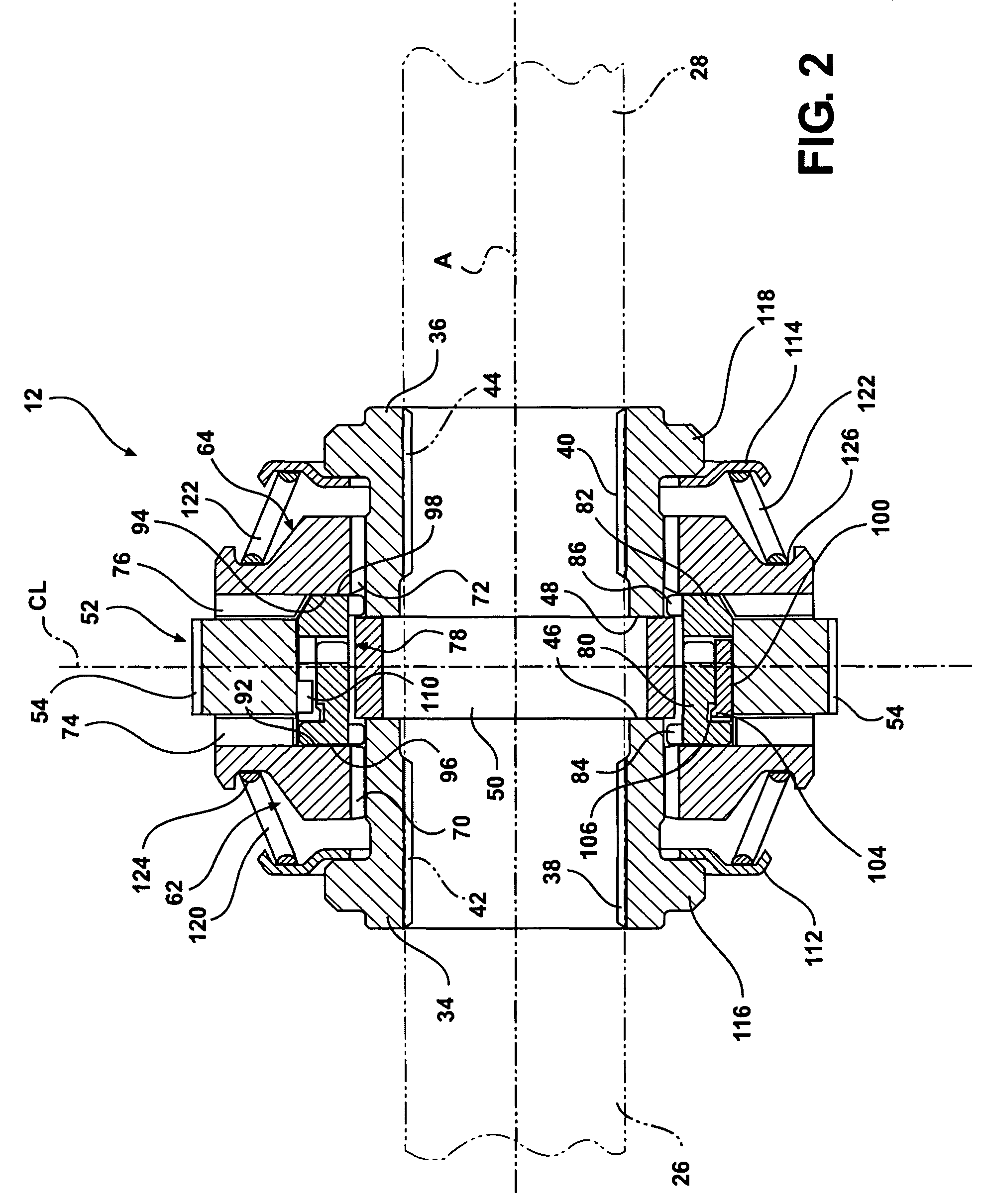
[0017]A representative portion of a vehicle drive train for supplying torque from a driveshaft (not shown) to a pair of aligned output shafts (shown in phantom at 26, 28 in FIGS. 1 and 2) is generally illustrated in FIGS. 1-4, where like numerals are used to designate like structure throughout the drawings. Those having ordinary skill in the art will appreciate from the description that follows that the purpose of the figures is to illustrate one example of the invention and are not meant to limit it. The drive train includes a locking differential mechanism, generally indicated at 12 in FIGS. 1 and 2, that is operatively supported in a differential housing, generally indicated at 14 in FIG. 1. The housing 14 may be configured in any suitable way commonly known in the art. For example, in the representative example illustrated in FIG. 1, the housing is defined by two pieces 16, 18 that are operatively mounted together at a flange coupling, generally indicated at 20. A ring gear (not...


PUM


Abstract

A locking differential mechanism for supplying torque from a driveshaft to a pair of aligned output shafts including a pair of side gears, a central driver, and a pair of clutch members operatively coupled for rotation with the corresponding one of the pair of side gears. A cam assembly includes a pair of cam members. Each of the pair of cam members includes a plurality of camming teeth extending toward the corresponding teeth on the opposed cam member. Each of the cam members is movable from a first position where the cam teeth are disposed in meshing relationship with respect to each other when the pair of side gears are rotating at substantially the same speed and a second position spaced axially from the first position along the associated side gear so as to move an associated clutch member from its first position to its second position out of driven relationship with the central driver in response to a difference in rotational speed of the associated pair of side gears.

Description

BACKGROUND OF THE INVENTION[0001]1. Field of the Invention[0002]The present invention is directed toward differentials, generally, and more specifically, toward locking differentials that operatively couple a pair of axle half shafts during most driving conditions and that automatically disengage one half shaft in response to predetermined speed differentials between the axles.[0003]2. Description of the Related Art[0004]A differential is a component of an axle assembly and is used to couple a pair of rotating half shafts which make up a portion of the axle assembly. The differential is driven by the driveshaft via a pinion gear that meshes with a ring gear mounted to the differential. In automotive applications, the differential allows the tires mounted at either end of an axle assembly to rotate at different speeds. This becomes important, for example, when the vehicle is turning. The outer tire travels over an arc of greater distance than the inner tire. Thus, the outer tire must...

Claims


Application Information

Patent Timeline
Patent Type & Authority Patents(United States)
IPC IPC(8): F16H48/12
CPCF16H48/142F16H48/14Y10T74/19005F16H48/20
Inventor BAWKS, JAMES ROBERT
Owner EATON INTELLIGENT POWER LTD
Why Eureka
Try Eureka