
Mooring device

a mooring device and mooring technology, applied in the direction of mooring equipment, anchors, vessel construction, etc., can solve the problems of further complications in mooring a vessel, no overall solution has been achieved, and troublesome mooring of the vessel

Inactive Publication Date: 2011-11-08
WANG ANCHOR
View PDF22 Cites 9 Cited by
  • Summary
  • Abstract
  • Description
  • Claims
  • Application Information

AI Technical Summary

Benefits of technology

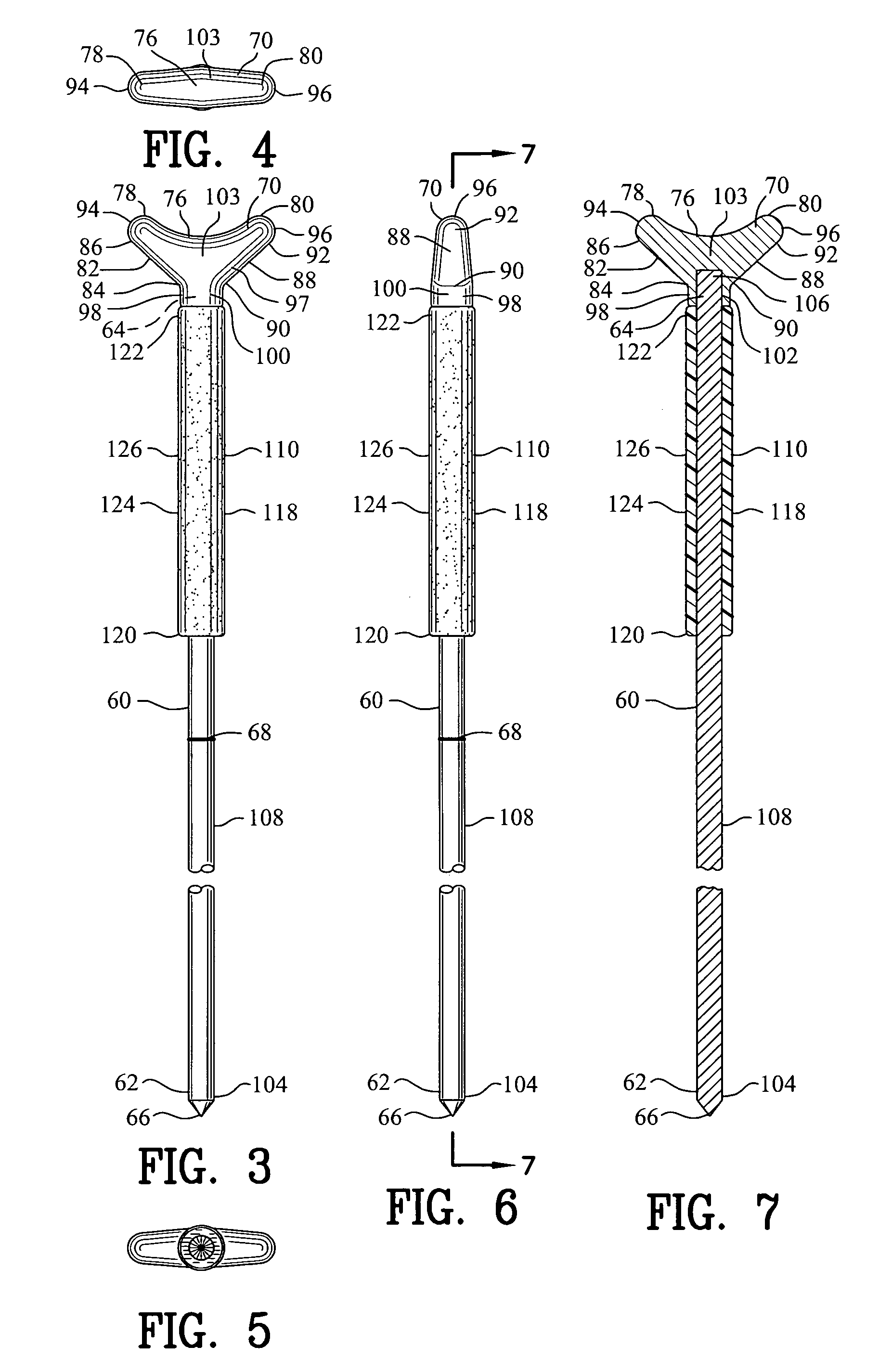
[0028]In a more specific embodiment of the invention, the first end of the shaft includes a first diameter and the second end of the shaft includes a second diameter. The first diameter is less than the second diameter. A continuous taper extends between the first end and the second end for reducing the descending vertical force required for the shaft to transverse the soil floor and into the layer of soil.

Problems solved by technology

However, if the vessel is located in open waters, mooring the vessel may be troublesome.
Furthermore, if the vessel is located within open swallow water and / or the vessel may be subject to within close proximity to the vessel resulting in further complications in mooring a vessel.
Although some of the devices of the prior art have addressed these problems none has successfully solved the overall issue.

Method used


Image

  • Mooring device
  • Mooring device
  • Mooring device

Examples


Embodiment Construction

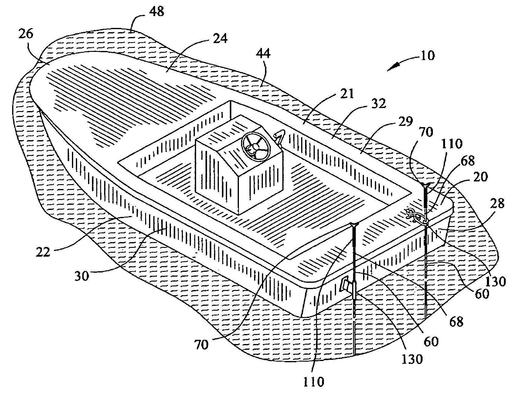
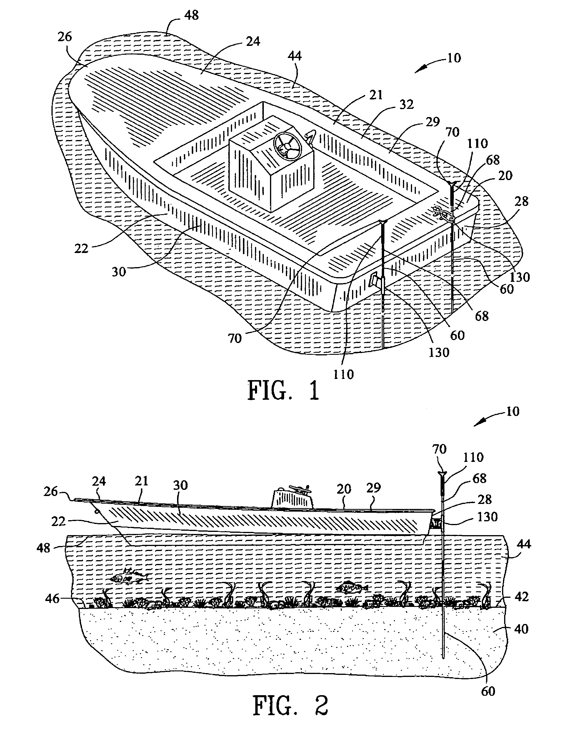
[0065]FIGS. 1-21 are various views of a mooring device 10 for securing a floating structure 20 to a layer of soil 40. The layer of soil 40 defines a soil floor 42 that supports a body of water 44. The body of water 44 defines a bottom edge 46 adjacent to the soil floor 42 and an upper edge 48. The upper edge 48 of the body of water 44 receives the floating structure 20. The body of water 44 is displaced by the floating structure 20 for providing a positive buoyancy to the floating structure 20. Preferably, the mooring device 10 is utilized within relatively shallow water, such that the mooring device 10 may extend between the floating structure 20 and the soil floor 42.

[0066]The floating structure 20 may include a vessel 21 having a hull 22 and deck 24. The hull 22 defines a bow 26, a stern 28, a port side 30 and a starboard side 32. The vessel 21 may support an individual 12 having a first hand 14 and a second hand 16. FIGS. 1, 2, 16-22 illustrate the vessel 21 comprising a flats b...


PUM


Abstract

A mooring device is disclosed for securing a floating structure to a layer of soil. A body of water is displaced by the vessel. The floating structure supports an individual having a first hand and a second hand. The mooring device comprises a shaft extending between a first end and a second end. A point is secured to the first end of the shaft for permitting the shaft to transverse the layer of soil. A handle is secured to the second end of the shaft for receiving a descending vertical force or an ascending vertical force. The handle includes a concave upper surface extending between a primary end and a secondary end for receiving the first hand and / or the second hand of the individual during the descending vertical force. The handle includes a first convex surface and a second convex surface.

Description

CROSS-REFERENCE TO RELATED APPLICATIONS[0001]This application claims benefit of U.S. Patent Provisional application Ser. No. 61 / 198,011 filed Oct. 31, 2008. All subject matter set forth in provisional application Ser. No. 61 / 198,011 is hereby incorporated by reference into the present application as if fully set forth herein.BACKGROUND OF THE INVENTION[0002]1. Field of the Invention[0003]This invention relates to a mooring device and more particularly to the boat mooring device for securing a boat to a soil layer.[0004]2. Background of the Invention[0005]Mooring a vessel allows the vessel to remain stationary within a body of water. Many types of devices may be used for mooring a vessel to a fixed object, such as a pier. However, if the vessel is located in open waters, mooring the vessel may be troublesome. Furthermore, if the vessel is located within open swallow water and / or the vessel may be subject to within close proximity to the vessel resulting in further complications in mo...

Claims


Application Information

Patent Timeline
IPC IPC(8): B63B21/00
CPCB63B21/22B63B21/29B63B2021/001
Inventor TYLISZ, THOMAS G.
Owner WANG ANCHOR
Learn More