Seat mounting structure for motorcycle, and motorcycle incorporating same

a technology for mounting structures and motorcycles, which is applied in the direction of bumpers, vehicular safety arrangments, bicycle equipment, etc., can solve the problems of increased difficulty in grasping the grips, and achieves the satisfaction of the appearance quality of the seat rail, easy and secure grasping, and convenient use.

Active Publication Date: 2011-11-08
HONDA MOTOR CO LTD
View PDF14 Cites 3 Cited by
  • Summary
  • Abstract
  • Description
  • Claims
  • Application Information

AI Technical Summary

Benefits of technology

[0014]In the present invention as disclosed the first aspect thereof—since the slotted openings are provided to the rear of the seat rail members, and the slotted openings are formed inwardly and upwardly from the outside in a vehicle width direction, fingers are inserted into the slotted opening directed upwardly when a passenger grasps the slotted opening for securing a hand, the inner surface of the slotted opening and the outside portions in the slotted opening of the seat rail member hit cushions of the passenger's fingers and the passenger's palm outside the slotted opening—the slotted opening can be easily and securely grasped.
[0015]The slotted opening is provided on the rear of the seat rail member inwardly and upwardly from the outside in the vehicle width direction, the portion of the seat rail member for securing a hand is not protruded outwardly. Accordingly, a dimension in the direction of the width of the right and left seat rail members can be restricted (inhibited). Also, since the seat rail member has no portion protruding sidewardly, a satisfactory appearance quality of the seat rail can be achieved.
[0016]In the present invention as disclosed in the second aspect thereof—since the rear fender separately formed between the right and left seat rail members is supported by the seat rail members and the convex portion protruding towards the slotted opening of each of the seat rail members corresponds to the slotted opening of the rear fender, the convex portion of the rear fender provided between the right and left seat rail members is fitted to the slotted opening of the seat rail, the rear fender is normally made of resin, and the slotted opening for securing a hand is made of resin—when the slotted opening is grasped for securing a hand, a feel of a grasp is satisfactory. Also, the slotted opening of the seat rail member in combination with the convex portion of the rear fender provides a grasping component which is easy to grasp for securing a hand.
[0017]In the present invention as disclosed in the third aspect thereof, since the slotted opening of the seat rail member is covered with the rear cowl from the outside, when viewed in a side view, the grasping component for securing a hand formed by the slotted opening of the rear of the seat rail and the convex portion of the rear fender is concealed from the outside. Further, since the side of the rear of the rear cowl is exposed in this grasping component, a satisfactory appearance quality of the seat rail members is achieved.
[0018]In the present invention as disclosed in the fourth aspect thereof, since the slotted opening of each of the seat rail members has substantially elliptical shape, when viewed in a top view, and since the convex portion of the rear fender surrounds the slotted opening, the whole circumference of the grasping component for securing a hand is surrounded, the whole circumferences of fingers and a palm are surrounded, and the portion for securing a hand can be easily and more securely grasped.

Problems solved by technology

The grips of the seat frames of the Japanese Patent document JP Patent No. 2706956, have problems because: they protrude on both sides of the seat frames; width between the seat frames may be widened since they are U-shaped and are directed upwardly; the semi-cylindrical outside faces each section swollen downwardly are gripped when a passenger seating on the rear of the seat grasps the grips, and accordingly, it is difficult to grasp the grips.
Also, when the sides of the grips are covered with a rear fender and a rear cowl because of appearance, the difficulty of grasping the grips is increased.

Method used


Image

  • Seat mounting structure for motorcycle, and motorcycle incorporating same
  • Seat mounting structure for motorcycle, and motorcycle incorporating same
  • Seat mounting structure for motorcycle, and motorcycle incorporating same

Examples


Embodiment Construction

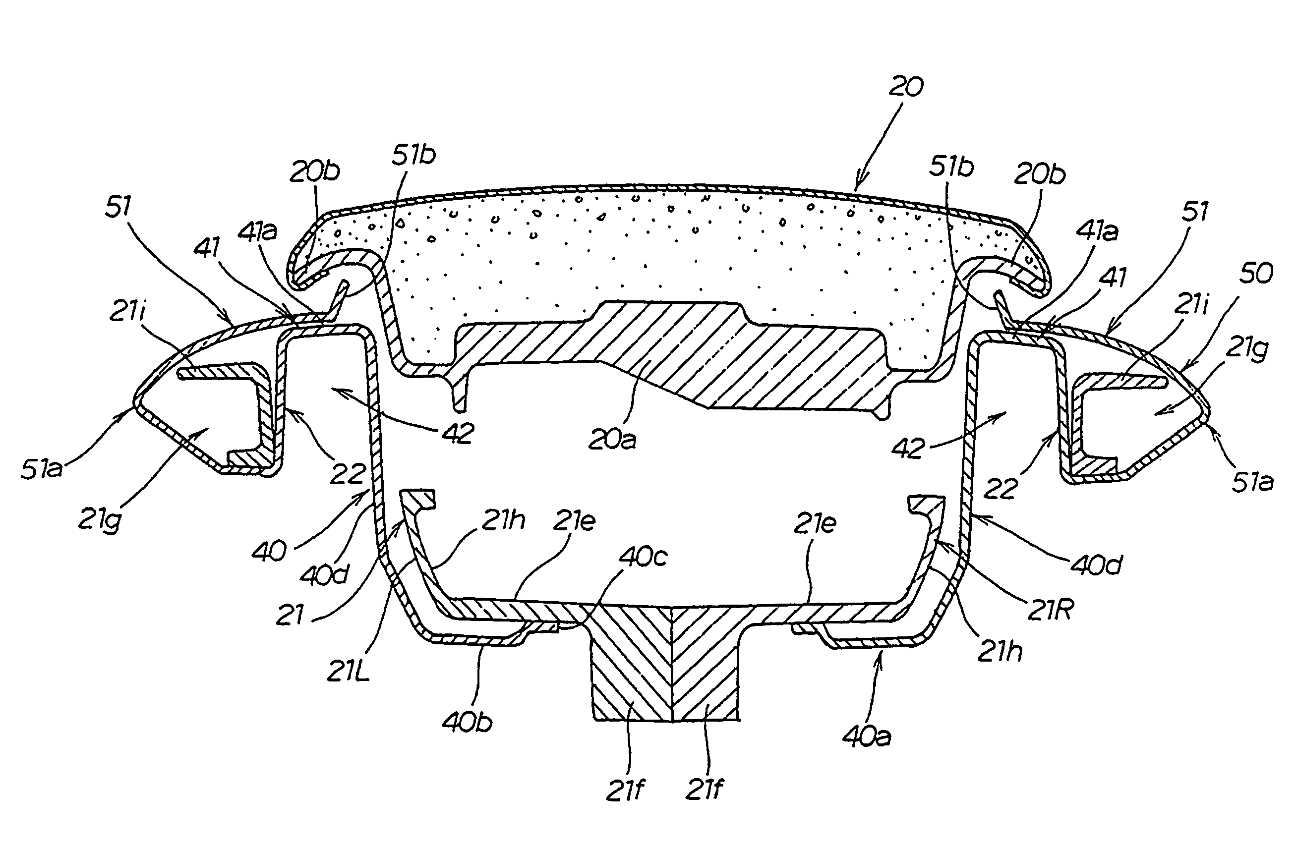
[0029]It should be understood that only structures considered necessary for illustrating selected embodiments of the present invention are described herein. Other conventional structures, and those of ancillary and auxiliary components of the system, will be known and understood by those skilled in the art.

[0030]An illustrative embodiment of the present invention is described below with reference to the attached drawings. In the drawings, Fr denotes a front side of the vehicle (a front traveling direction of a vehicle), Rr denotes the rear direction opposite to the front traveling direction, R denotes the right side based upon a rider's position, while normally operating the vehicle, and L denotes the left side based upon the rider's position.

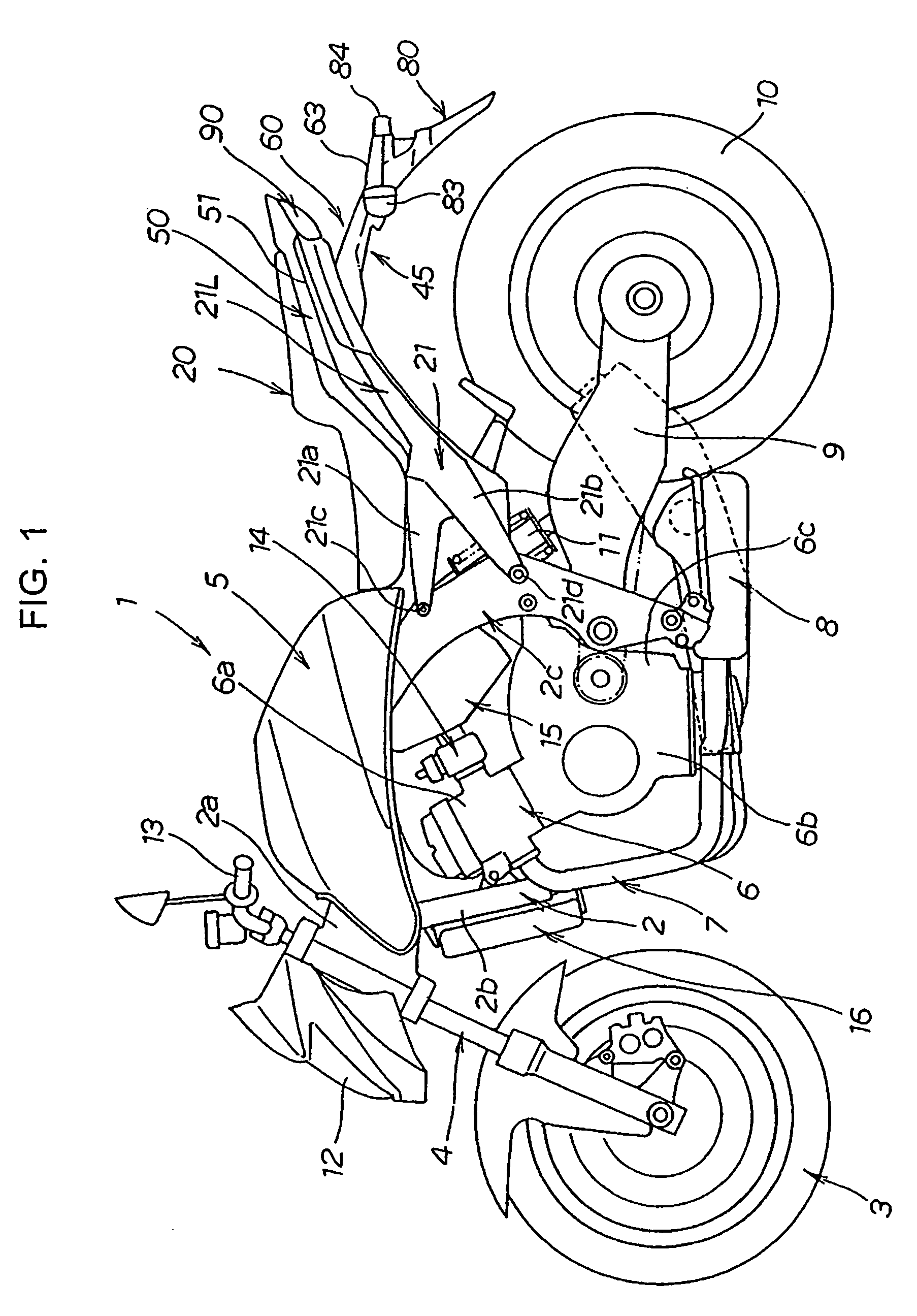
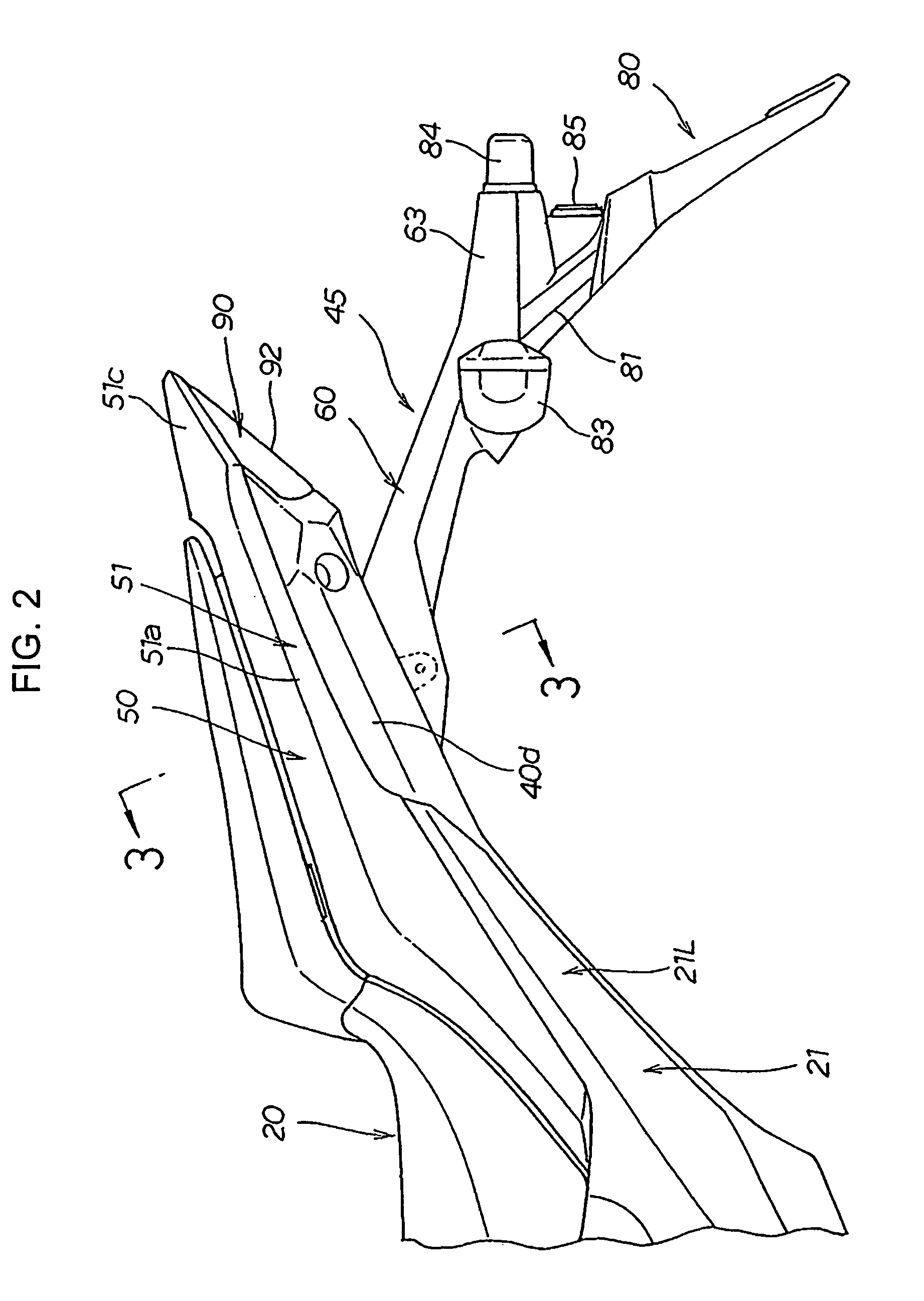
[0031]FIG. 1 is a schematic side view showing a motorcycle having a seat mounting structure having a seat rail according to the present invention. Referring to drawing, an outline of the motorcycle is described below.

[0032]In the motorcycle 1, ...


PUM


Abstract

A seat mounting structure having a seat rail for supporting a seat of a motorcycle includes seat rail members having front end portions thereof supported by an intermediate portion of a vehicle body frame. Each of the seat rail members extends rearwardly from the intermediate portion of the vehicle body frame. Each of the seat rail members has a slotted opening formed thereon at a rear portion thereof. The slotted openings are formed inwardly and upwardly from an outer portion of the seat rail members in a vehicle width direction.

Description

CROSS-REFERENCE TO RELATED APPLICATIONS[0001]The present application claims priority under 35 USC §119 based on Japanese patent application No. 2007-286422, filed on Nov. 2, 2007. The entire subject matter of this priority document is incorporated by reference herein.BACKGROUND OF THE INVENTION[0002]1. Field of the Invention[0003]The present invention relates to a seat mounting structure for a motorcycle, and to a motorcycle incorporating same. More particularly, the present invention relates to seat mounting structure including a seat rail having a slotted opening formed therein.[0004]2. Description of the Background Art[0005]There are several known seat mounting structures having seat rail members supporting a seat of a motorcycle. The seat rail is provided at a rearward portion of a vehicle (motorcycle) body, and is configured to support a seat thereon. The seat rail is extended rearwardly from a rear of a main frame of the motorcycle. The main frame forms a front half of the bod...

Claims


Application Information

Patent Timeline
Patent Type & Authority Patents(United States)
IPC IPC(8): B62J1/08B62K11/02B62J1/28B62J15/00B62J23/00B62K11/04
CPCB62J15/00B62K11/04B62K19/30
Inventor NISHIJIMA, TOMOKITSUTSUI, NORIYOSHI
Owner HONDA MOTOR CO LTD
Why Eureka
Try Eureka