Device for electrically conductive contacting a pipe

a technology of electrically conductive contact and pipe, which is applied in the direction of connection, connection insulation, electrical apparatus, etc., can solve the problems of no effect, creep and deterioration of elastic insulating materials, etc., and achieve the enforcement of the stability and rigidity of the end part, the effect of sufficient space for elastic insulating materials and a higher force or torqu

Inactive Publication Date: 2011-11-08
RPX CORP
View PDF12 Cites 6 Cited by
  • Summary
  • Abstract
  • Description
  • Claims
  • Application Information

AI Technical Summary

Benefits of technology

[0010]The device is furthermore particularly advantageous, as, for example with respect to the device disclosed in EP 0 744 788, no additional manufacturing step is required for the production of the device in accordance with the invention. Furthermore, no additional piece-parts have to be produced and inserted into an earthing kit comprising such a device. Thus, the device provides a cost effective and simple solution that does not have the disadvantages described in the background section.
[0014]In accordance with an embodiment of the invention, the first region is bordered by the shoulder or by the shoulders in case both end parts comprise a shoulder. The usage of a shoulder provides the advantage that sufficient space for the elastic insulating material is provided in between the end parts of the clamp.
[0015]In accordance with an embodiment of the invention, at least one of the end parts comprises in the vicinity of the parts of the closing device a reinforcing extension. The reinforcing extension contributes to an enforcement of the stability and rigidity of the end part at least in the vicinity of the parts of the closing device and therefore allows for an application of a higher force or torque on the parts of the closing devices for fixing the device in the assembly position.
[0017]In accordance with an embodiment of the invention, at least one of the end parts comprises at least two layers of the band shaped metallic clamp. This leads to an increase of the stability and rigidness of the end parts.

Problems solved by technology

As there is no insulating material in between the two end parts at least in the vicinity of the parts of the closing device, the elastic insulating material which is subject to creep and deterioration due to aging effects does not have any effect on the fixed and defined force used to clamp the end parts together by use the closing device.

Method used


Image

  • Device for electrically conductive contacting a pipe
  • Device for electrically conductive contacting a pipe
  • Device for electrically conductive contacting a pipe

Examples


Embodiment Construction

[0041]Reference numerals of analogous elements are identical in the FIGS. 1-10.

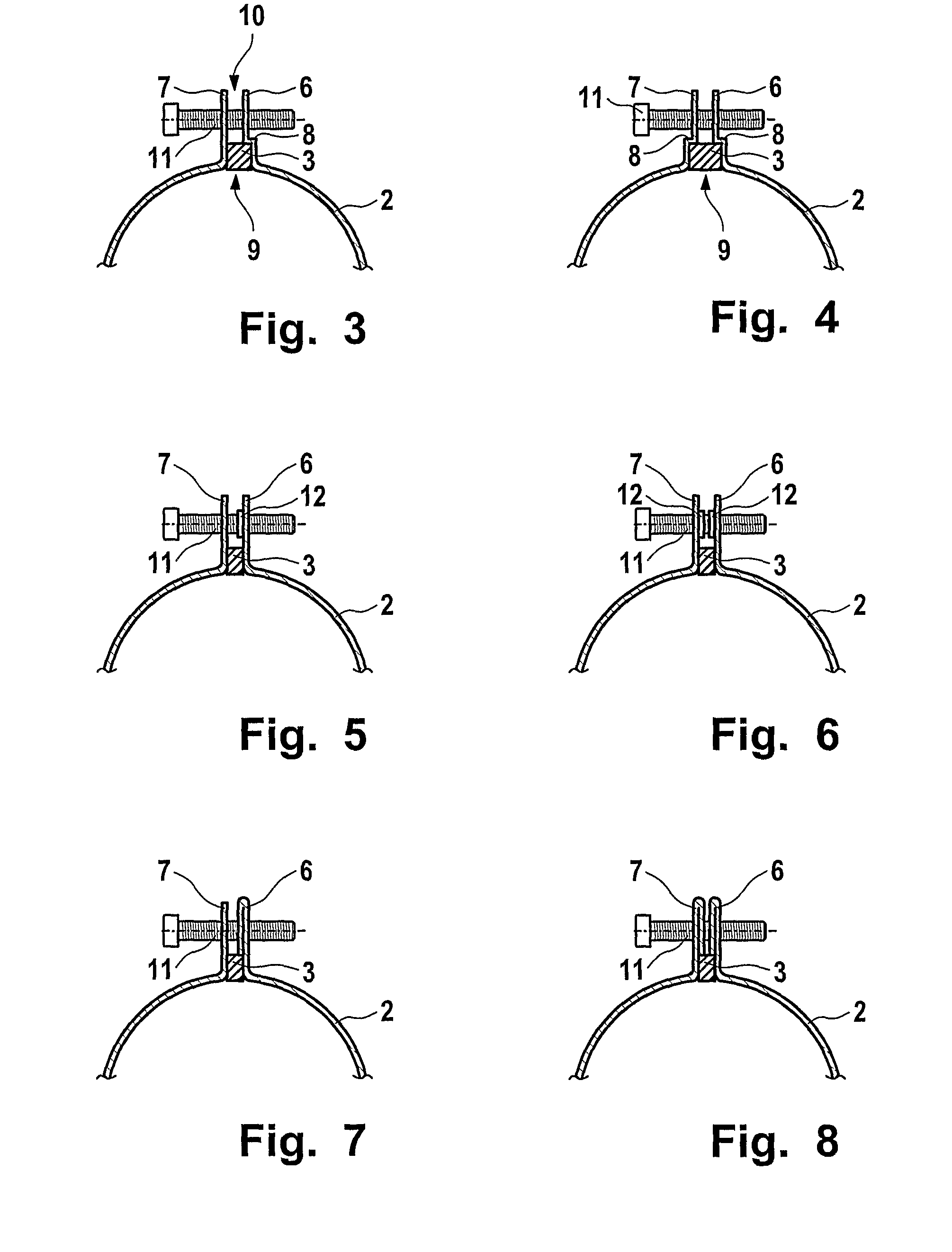
[0042]FIG. 3 shows a cross sectional view of a portion of a device in accordance with the invention. The device comprises a clamp 2 of which only a part is shown. The clamp 2 consists of a metallic material, e.g., copper or stainless steel, and is band shaped. The clamp 2 has end parts 6 and 7. The end part 6 comprises a shoulder 8. Elastic insulating material 3 is placed in between the end parts 6 and 7. The space between the end parts 6 and 7 can therefore be divided into a first region 9 and a second region 10. The first region 9 is bordered in the assembly position by the pipe which is not shown in FIG. 3 and by a fraction of the inner surface of each end part as indicated by the scratched region in FIG. 3 that relates also to the insulating material 3. The first region is bordered in particular by the shoulder 8.

[0043]The second region 10 is bordered by the remaining inner surfaces of the end parts 6...


PUM


Abstract

There is provided a device for electrically conductive contacting of a pipe having a band shaped metallic clamp (2) with two end parts (6, 7), wherein the clamp is equipped with parts of a closing device (11, 13, 14) at both end parts. The device has a separator (4) made from electrically conductive material, wherein the separator is deformable under pressure and wherein the separator is attached to the inner surface of the clamp. The device further comprises insulating material (3), wherein the clamp is embedded in the insulating material leaving free the inner surface required for making contact with the pipe. Furthermore, the embedded material leaves free both end parts of the clamp enabling a direct contact between both end parts in an assembly position of the device around the pipe.

Description

FIELD OF THE INVENTION[0001]The invention relates to a device for electrically conductive contacting of a pipe and to an earthing kit comprising such a device.BACKGROUND[0002]Devices for electrically conductive contacting of a pipe are for example employed to ground the pipe. Of particular relevance is such a grounding for electrical cables that have a metallic pipe as electrical conductor. Such a pipe can for example relate to the outer conductor of a coaxial cable, e.g. a coaxial high frequency (HF)-cable.[0003]EP 1 352 451 discloses a device for electrically conductively contacting a sectionally bared external conductor of a coaxial cable. The device has a basic body constructed as a clip which can be fixed around the cable to be contacted. The basic body is designed so as to be open in the peripheral direction and comprises at its ends bent or turned taps consisting at least partially of metal and on the faces of which facing one another in the assembled position sealing faces m...

Claims


Application Information

Patent Timeline
Patent Type & Authority Patents(United States)
IPC IPC(8): H01R4/28
CPCH01R4/643H01R4/70
Inventor BERNASCH, PETERMAHLANDT, ERHARD
Owner RPX CORP
Why Eureka
Try Eureka