

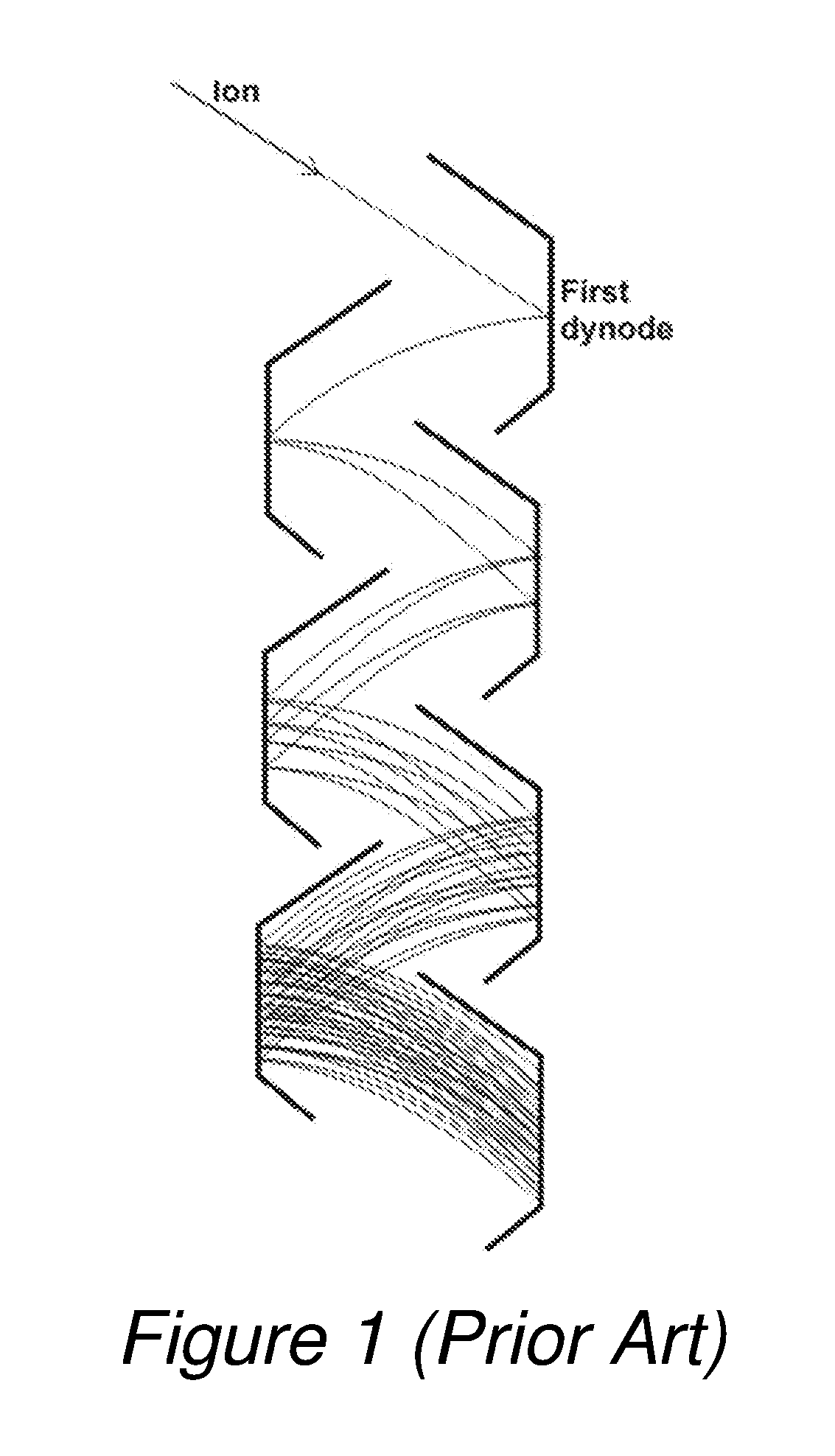
Mass spectrometer having multi-dynode multiplier(s) of high dynamic range operation
a multi-dynode multiplier and mass spectrometer technology, applied in the field of secondary electron multipliers, can solve the problems of complicated circuitry, cost, time is not always available, and the implementation is costly, and achieves fast signal response, large dynamic range, and simple and cost-effective
- Summary
- Abstract
- Description
- Claims
- Application Information
AI Technical Summary
Benefits of technology
Problems solved by technology
Method used
Image

Examples
Embodiment Construction
[0038]While the invention has been shown and described with reference to a number of different embodiments thereof, it will be recognized by those of skill in the art that various changes in form and detail may be made herein without departing from the scope of the invention as defined by the appended claims.
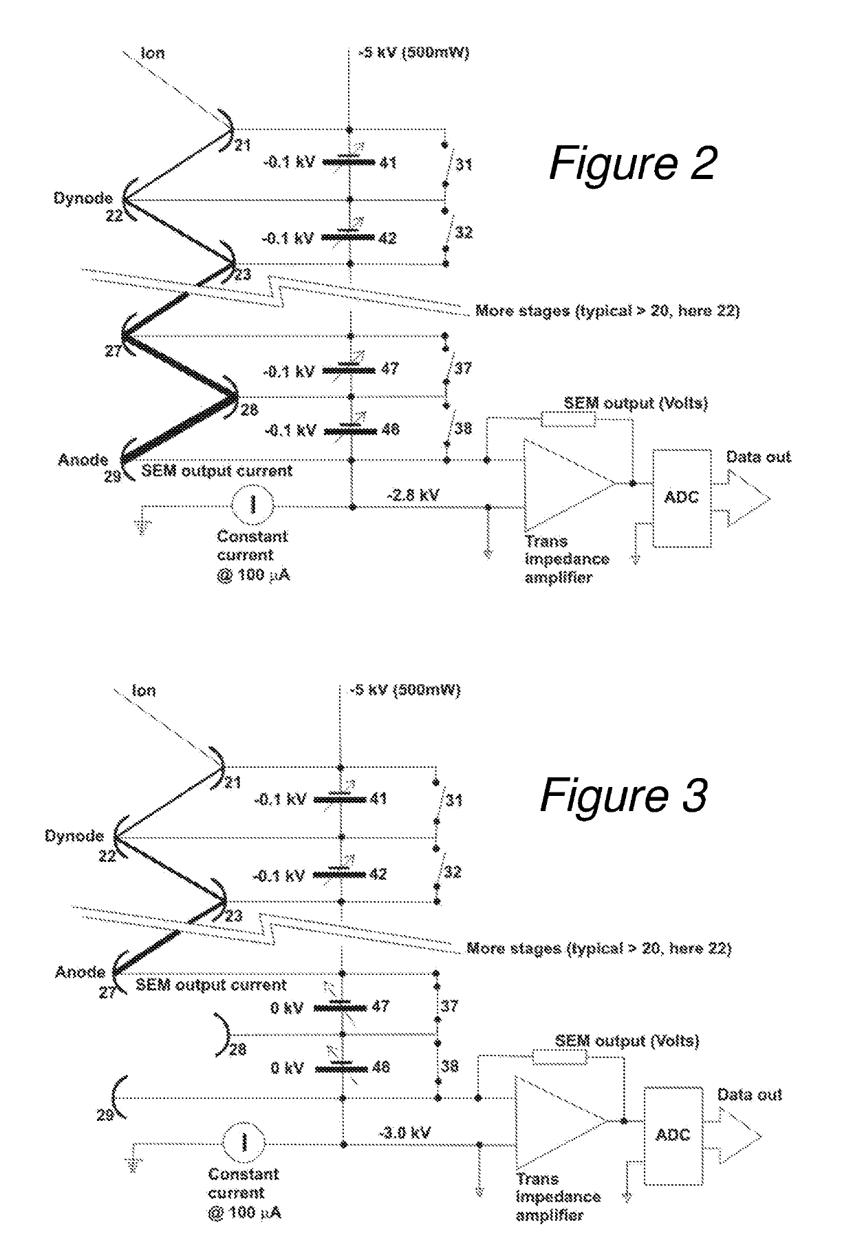
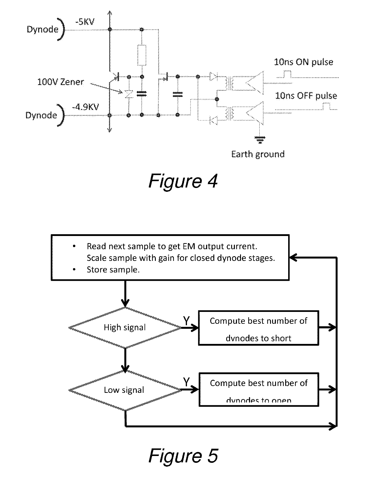
[0039]The principle of the invention will be described mainly with reference to the embodiment presented in FIGS. 2 and 3, showing schematically discrete multiplier dynodes (21) to (29), discrete voltage supply circuits (41) to (48), and discrete short-cut switches (31) to (38). For simplification, the voltage supply circuits (41) to (48) are drawn symbolically as controllable batteries, though using other sources of energy is conceivable. A more detailed depiction of the circuitry is also shown by way of example in FIG. 4.
[0040]The voltage values in the drawings may correspond to a multiplier with 22 dynode stages, but this number of stages is not reflected by the reference num...
PUM
 Abstract
Description
Claims
Application Information