Branch vessel prosthesis with a roll-up sealing assembly

a technology of sealing assembly and blood vessel, applied in the field of endoluminal medical devices and procedures, can solve the problems of internal bleeding, potentially life-threatening conditions, weak, thin blood vessel walls, etc., and achieve the effect of low profil

Active Publication Date: 2011-11-08
MEDTRONIC VASCULAR INC
View PDF106 Cites 207 Cited by
  • Summary
  • Abstract
  • Description
  • Claims
  • Application Information

AI Technical Summary

Problems solved by technology

Aneurysms result from weak, thinned blood vessel walls that “balloon” or expand due to aging, disease and / or blood pressure in the vessel.
Consequently, aneurysmal vessels have a potential to rupture, causing internal bleeding and potentially life threatening conditions.
Unfortunately, not all patients diagnosed with aortic aneurysms are presently considered to be candidates for endovascular grafting.
This is largely due to the fact that most of the endovascular grafting systems of the prior art are not designed for use in regions of the aorta from which side branches extend.
The deployment of endovascular grafts within regions of the aorta from which branch arteries extend presents additional technical challenges because, in those cases, the endovascular graft must be designed, implanted, and maintained in a manner which does not impair the flow of blood into the branch arteries.
As a result, the edges of the graft surrounding the fenestrations are prone to: i) the leakage of blood into the space between the outer surface of the aortic graft and the surrounding aortic wall; or ii) post-implantation migration or movement of the stent graft causing misalignment of the fenestration(s) and the branch artery(ies), which may result in impaired flow into the branch artery(ies).
An especially challenging area to deploy and seal branch grafts is the aortic arch.

Method used


Image

  • Branch vessel prosthesis with a roll-up sealing assembly
  • Branch vessel prosthesis with a roll-up sealing assembly
  • Branch vessel prosthesis with a roll-up sealing assembly

Examples


Embodiment Construction

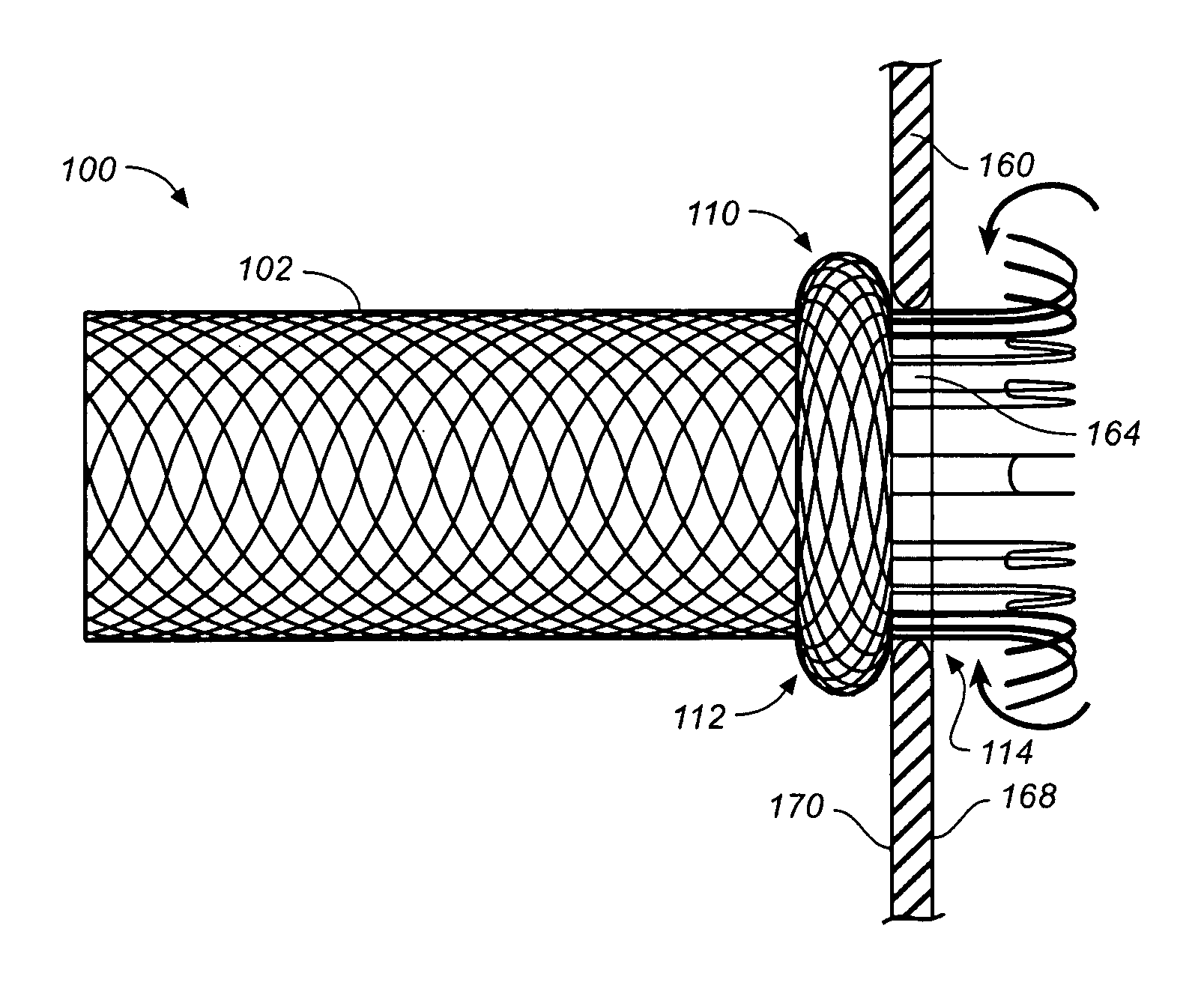
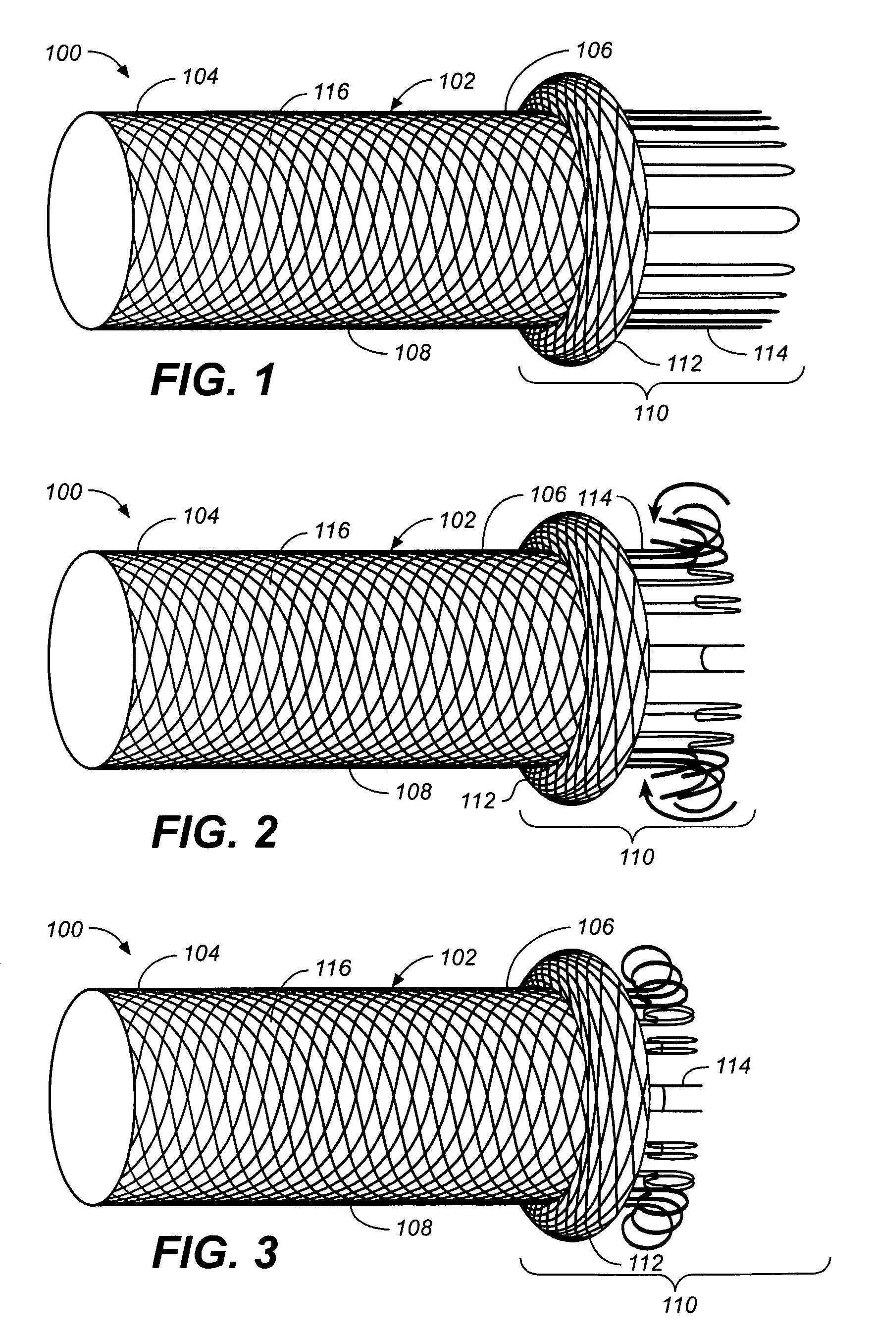
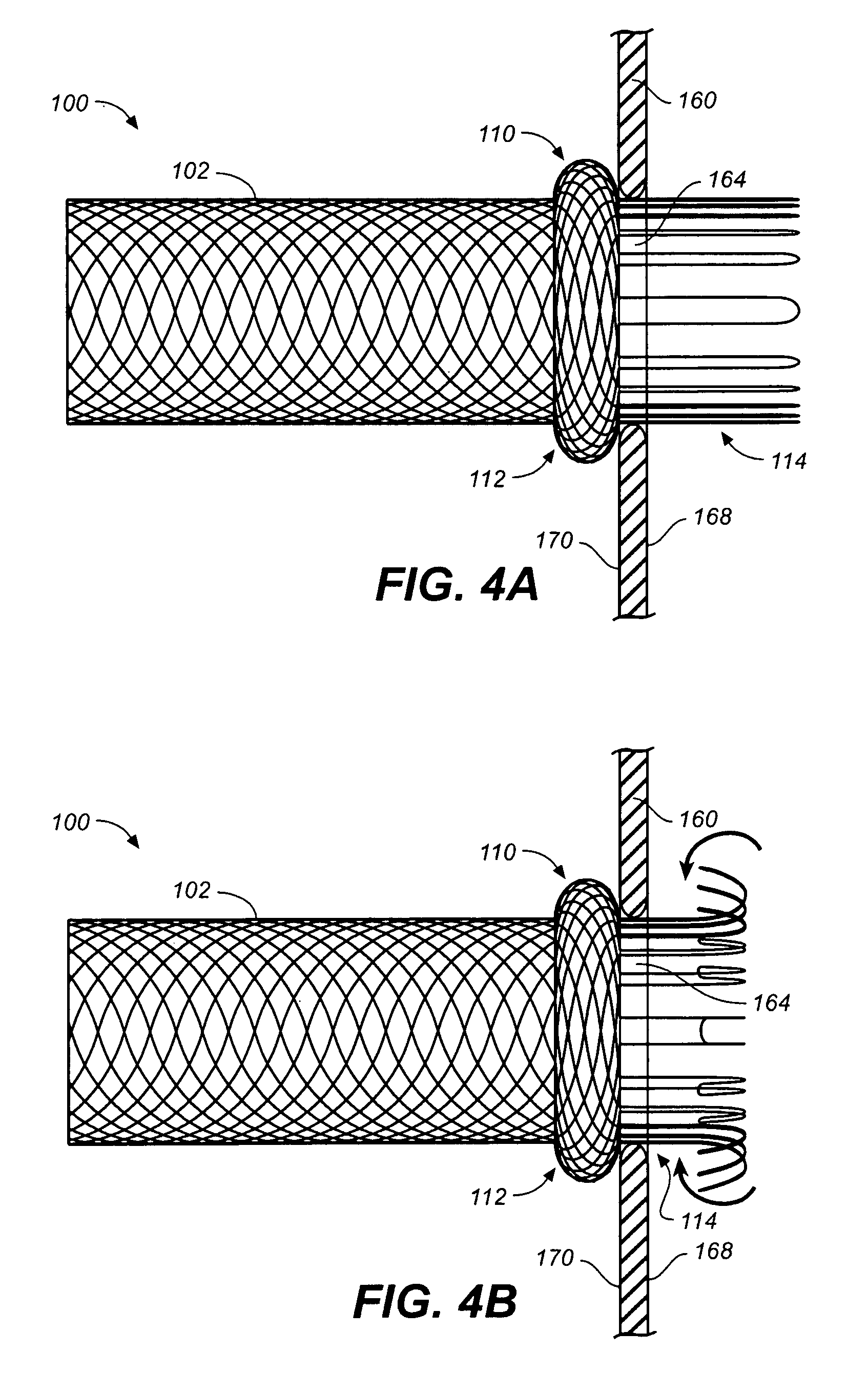
[0036]Specific embodiments are now described with reference to the figures, wherein like reference numbers indicate identical or functionally similar elements. Unless otherwise indicated, with respect to intravascular prostheses described herein such as branch prosthesis 100, the terms “distal” and “proximal” are used in the following description with respect to a position or direction relative to the heart. “Distal” and “distally” are positions distant from or in a direction away from the heart by blood flow path, and “proximal” and “proximally” are positions near or in a direction toward the heart by blood flow path. With respect to delivery systems described herein, the terms “distal” and “proximal” are used in the following description with respect to a position or direction relative to the treating clinician. “Distal” and “distally” are positions distant from or in a direction away from the clinician, and “proximal” and “proximally” are positions near or in a direction toward t...


PUM


Abstract

A branch prosthesis configured for placement in a branch vessel includes an expandable tubular body portion, an expandable annular flange attached to a proximal end of the body portion, and a sealing sleeve proximally extending from the annular flange. The sealing sleeve is adapted to deform to a generally straight cylindrical hollow shape during implantation. When deployed, the sealing sleeve rolls up to a tightly-wound coil that bears against the annular flange. When used in conjunction with a main prosthesis having a side opening and deployed within in a main vessel, the annular flange of the branch prosthesis engages an outer surface of the main prosthesis around a perimeter of the side opening and the sealing sleeve engages an inner surface of the main prosthesis around the perimeter of the side opening to form a fluid-tight seal between the main prosthesis and the branch prosthesis.

Description

FIELD OF THE INVENTION[0001]This invention relates generally to endoluminal medical devices and procedures, and more particularly to a branch vessel prosthesis having a rollup flange for creating a fluid-tight seal with a main vessel prosthesis.BACKGROUND[0002]Prostheses for implantation in blood vessels or other similar organs of the living body are, in general, well known in the medical art. For example, prosthetic vascular grafts constructed of biocompatible materials, such as Dacron or expanded, porous polytetrafluoroethylene (PTFE) tubing, have been employed to replace or bypass damaged or occluded natural blood vessels. In general, endovascular grafts typically include a graft anchoring component that operates to hold the tubular graft in its intended position within the blood vessel. Most commonly, the graft anchoring component is one or more radially compressible stents that are radially expanded in situ to anchor the tubular graft to the wall of a blood vessel or anatomical...

Claims


Application Information

Patent Timeline
Patent Type & Authority Patents(United States)
IPC IPC(8): A61F2/06A61F2/82
CPCA61F2/064D04C1/06A61F2/07D10B2509/06A61F2002/061A61F2002/821A61F2002/8486A61F2240/001A61F2250/0039A61F2250/006A61F2/89A61F2/90A61F2002/072A61F2002/075A61F2220/0058
Inventor BRUSZEWSKI, WALTERMAFI, MASOUMEHSHAMLOU, SHAHRAM
Owner MEDTRONIC VASCULAR INC
Why Eureka
Try Eureka