
Prosthetic anchor and method of making same

a technology of prosthetics and tendons, applied in the field of prosthetic anchors, can solve the problems of requiring a substantial thickness, affecting the stability of prosthetic flexible tension members, and tendons or ligaments, and requiring fatigue failure and breakage over the immense number of stress cycles, so as to improve the stress distribution

Inactive Publication Date: 2011-11-08
UNIVERSITY OF CINCINNATI
View PDF65 Cites 25 Cited by
  • Summary
  • Abstract
  • Description
  • Claims
  • Application Information

AI Technical Summary

Benefits of technology

The present invention provides a prosthetic anchor that can be used in various surgical procedures to connect a relatively rigid structure, such as a tendon or ligament, to a human or animal body. The anchor has a thin, wafer-like design with a central layer that incorporates multiple bundles of fibers, which form a matrix. The fibers are packed close to each other and concentric to the central layer, and the anchor can be fixed to a rigid structure using screws or other mechanical fixation methods. The surface membranes covering the anchor can be smooth or textured to encourage or discourage tissue adherence. The anchor is designed to distribute stress evenly and can be used in cardiac and plastic surgery procedures.

Problems solved by technology

Fixation of prosthetic flexible tension members, such as tendons or ligaments, to relatively rigid structures is a serious problem.
While this allows greater control of local stress concentration than does a simple bone-hole, in theory it delivers extremely high shear stresses to the tension member locally, which may cause fatigue failure and breakage over the immense number of stress cycles expected to be required.
A knob-loop fixation device has been previously disclosed to address the stress-concentration issue, but requires a substantial thickness that may be disadvantageous.
Such thickness could be problematic in some cardiac surgical, plastic and reconstructive surgical, or orthopaedic surgical devices, for example, in regions where skin is quite close to a coupled bone (e.g., the frontal bone in the case of a cosmetic surgical ‘brow lift’ prosthesis and the olecrenon in an orthopaedic surgical elbow prosthesis).

Method used


Image

  • Prosthetic anchor and method of making same
  • Prosthetic anchor and method of making same
  • Prosthetic anchor and method of making same

Examples


Embodiment Construction

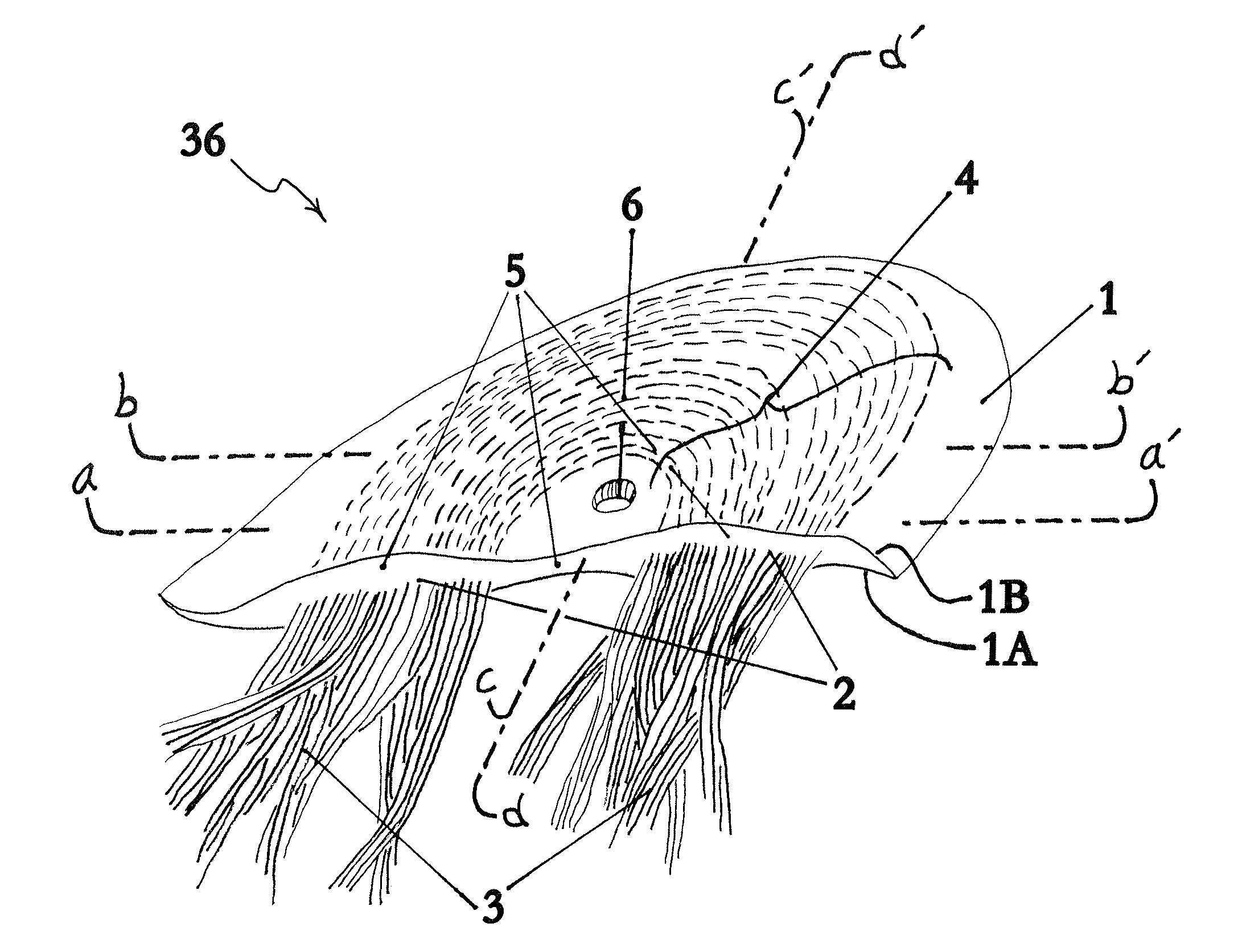
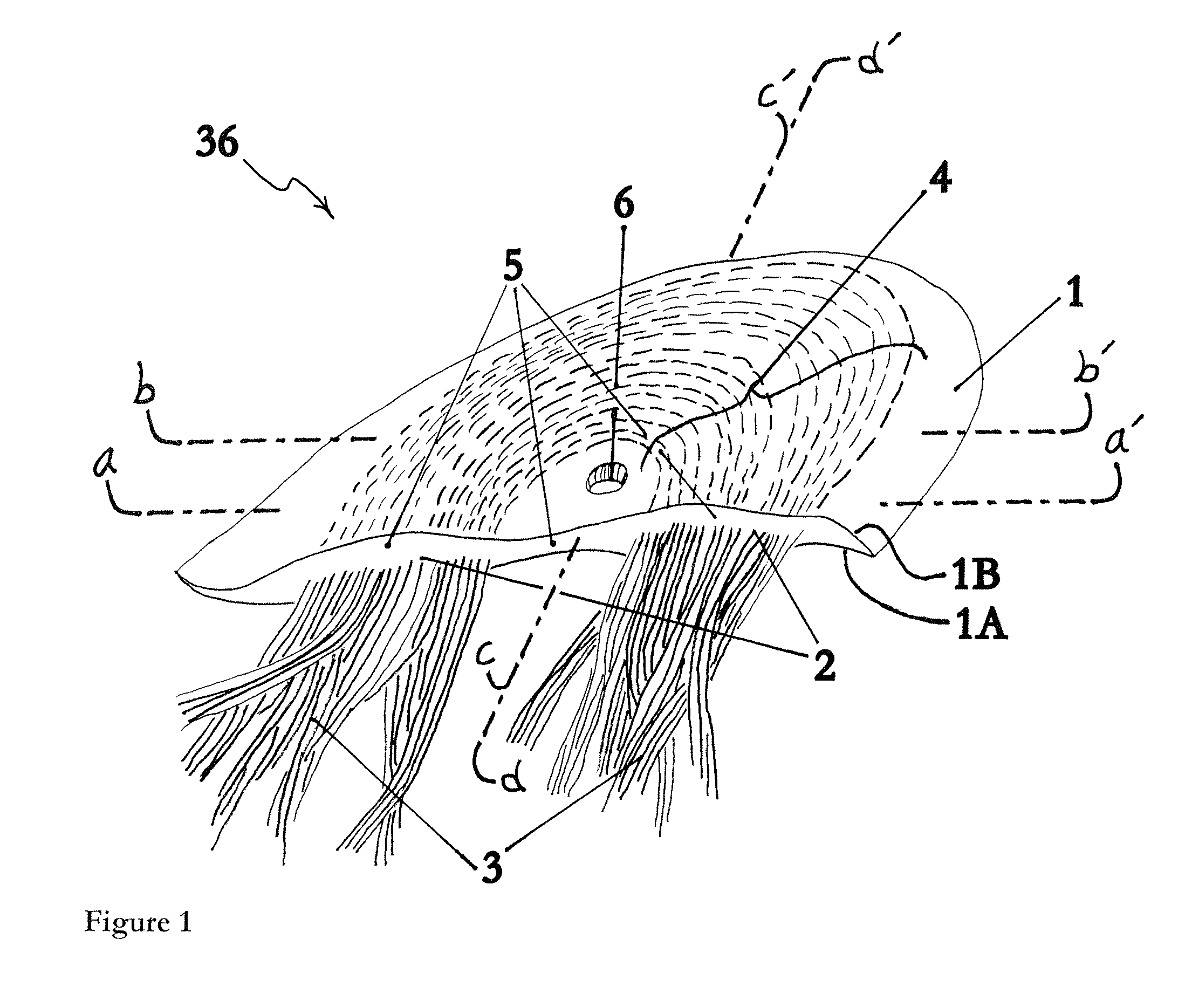
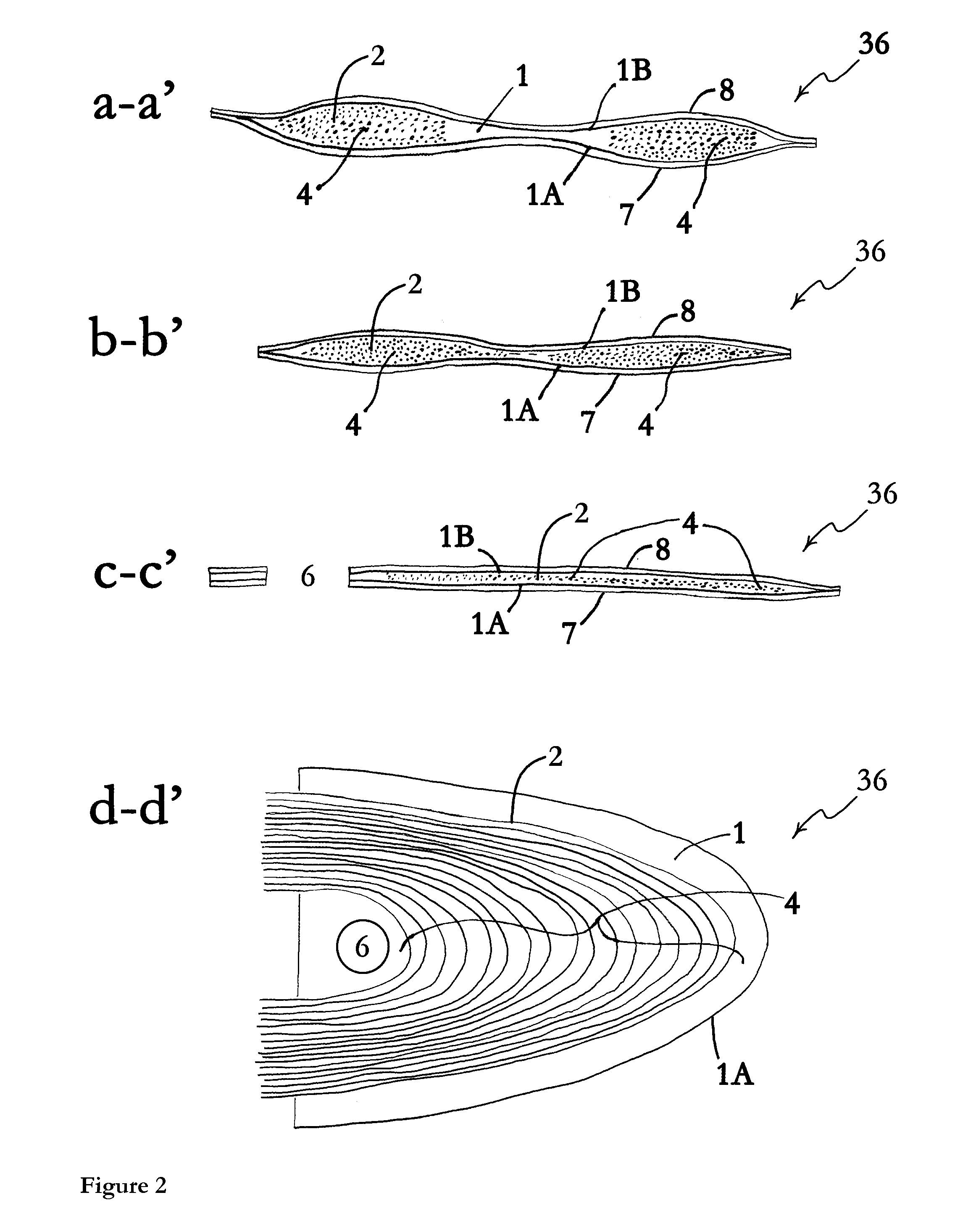
Part Numbers1. central layer; 1a. opposing first surface; 1b. opposing second surface2. embedded fibers3. entering and exiting fiber bundles4. concentric pathways of fibers in central layer5. thickened edge of central layer into which fiber bundles enter6. optional central opening in central layer7. deep (semi-rigid) membrane8. superficial (semi-rigid) membrane9. face of deep membrane configured for adherence to central layer10. face of superficial membrane configured for adherence to central layer11. face of deep membrane configured for adherence to a bone or to a prosthesis12. face of superficial membrane configured for non-adherence to contiguous living tissue13. surface, or surface replica14. mold made to mate part 13, of a soft elastomeric material such as a polyurethane or silicone rubber. Part 14 is termed “fabrication part A” in the continuing description.15. replica of the applicable surface of part 13, termed “fabrication part B” in description16. clay, or clay-like moldab...


PUM


Abstract

The present invention is directed towards a prosthetic anchor (36) including a central layer (1) through which embedded fibers (2), such as artificial tendons, pass in defined pathways (4), a ‘deep’ surface membrane (7) which interfaces with a hard structure, whether that is a prosthesis, a bone, or other hard tissue, and a ‘superficial’ surface membrane (8) which interfaces adjacent tissue and may be configured to adhere or not to adhere to that tissue. The central layer (1) is positioned intermediate the surface membranes (7, 8) which are mechanically and / or adherently attached thereto. Also, non-limiting examples of methods of fabrication and of affixing the anchor (36) to a relatively rigid structure, natural or prosthetic, in a human or animal body with improved stress distribution in the fixed tension member end are taught.

Description

FIELD OF THE INVENTIONThe present invention relates generally to fixation of artificial tendons, transmitting force from skeletal muscles, either to energy converters powering cardiac or other devices, or to natural or prosthetic bones, and more particularly, to a prosthetic anchor, to methods of fabrication, and to means of fixing thereof to a relatively rigid structure, natural or prosthetic, in a human or animal body with improved stress distribution in a fixed tension member, e.g. fixed fibers defining a tendon or ligament.BACKGROUND OF THE INVENTIONFixation of prosthetic flexible tension members, such as tendons or ligaments, to relatively rigid structures is a serious problem. A notable example is the use of artificial ligaments, such as the Leeds-Keio anterior cruciate ligament replacement in the knee. In that example, published experience with the usual means of bone fixation—drilling a hole in the tibia, inserting the ligament, and securing with a suture or pin—has included...

Claims


Application Information

Patent Timeline
Patent Type & Authority Patents(United States)
IPC IPC(8): A61F2/08
CPCA61F2/0811A61F2002/0858A61F2002/087A61F2002/0888
Inventor MELVIN, DAVID BOYD
Owner UNIVERSITY OF CINCINNATI
Learn More