Apparatus and method for measuring load current using a ground fault sensing transformer

a load current technology, applied in the field of current sensors, can solve the problems of non-uniform magnetic field intensity and localized flux densities of ferrite cores and achieve the effect of reducing the number of ground fault sensing transformers

Active Publication Date: 2011-11-08
SCHNEIDER ELECTRIC USA INC
View PDF3 Cites 24 Cited by
  • Summary
  • Abstract
  • Description
  • Claims
  • Application Information

AI Technical Summary

Problems solved by technology

The circuit exploits the fact that the localized magnetic field intensities in a ferrite core of the ground fault sensing transformer are not uniform when load current passes through the conductors that pass through the center of the transformer.
As a result, the non-uniform magnetic field produces localized changes in flux densities over a cycle of load current that can be detected by disturbing a resonant circuit and measuring the frequency and losses in the resulting decaying sinusoidal signal produced by the “ringing” resonant circuit.

Method used


Image

  • Apparatus and method for measuring load current using a ground fault sensing transformer
  • Apparatus and method for measuring load current using a ground fault sensing transformer
  • Apparatus and method for measuring load current using a ground fault sensing transformer

Examples


Embodiment Construction

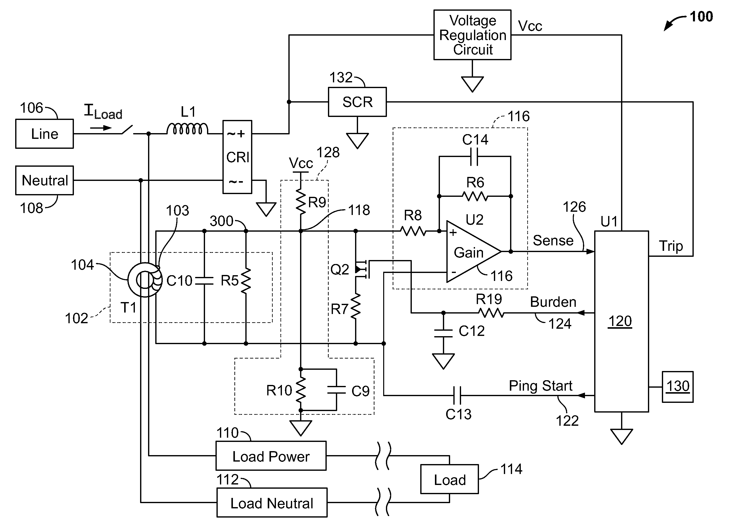
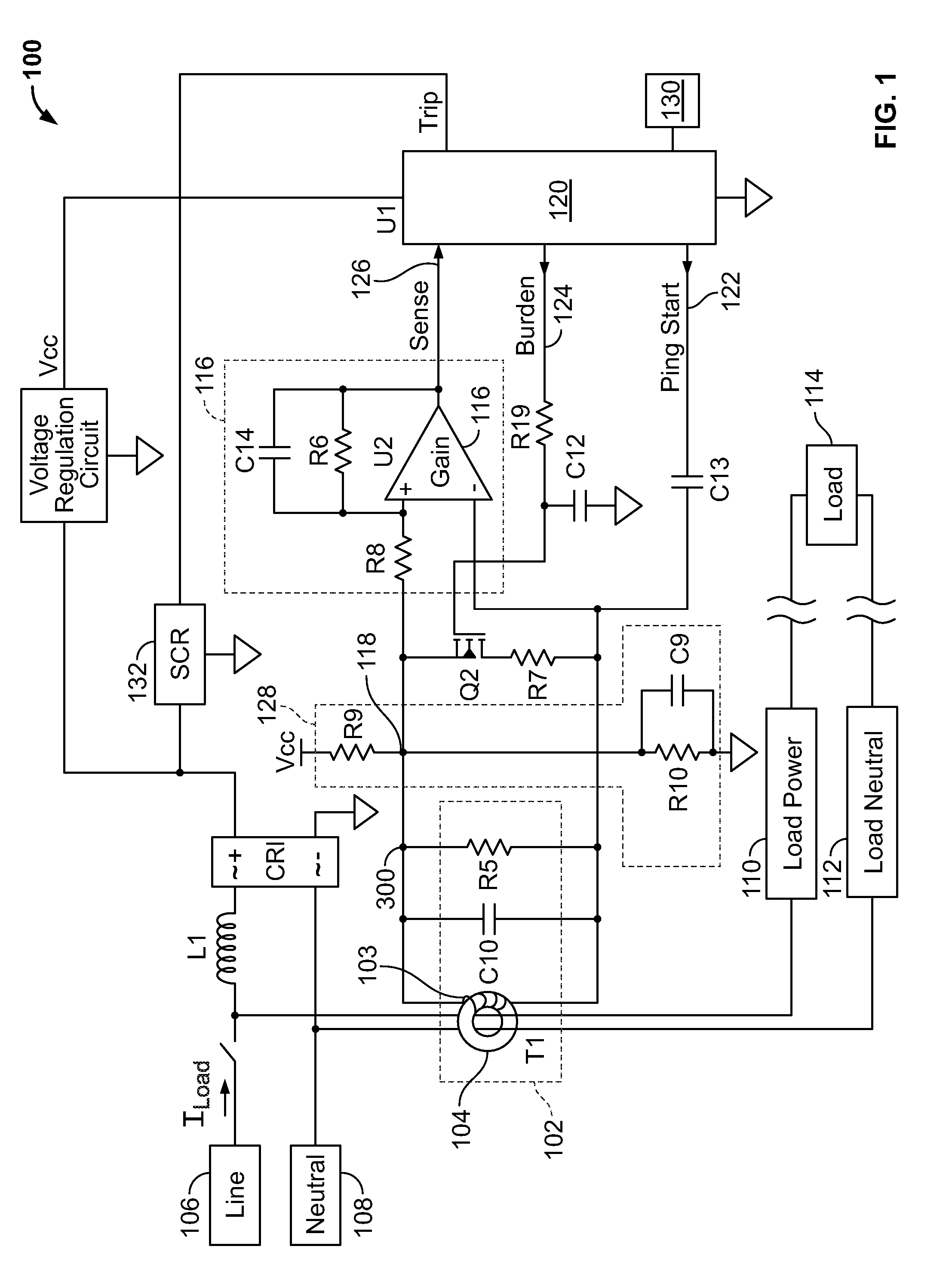
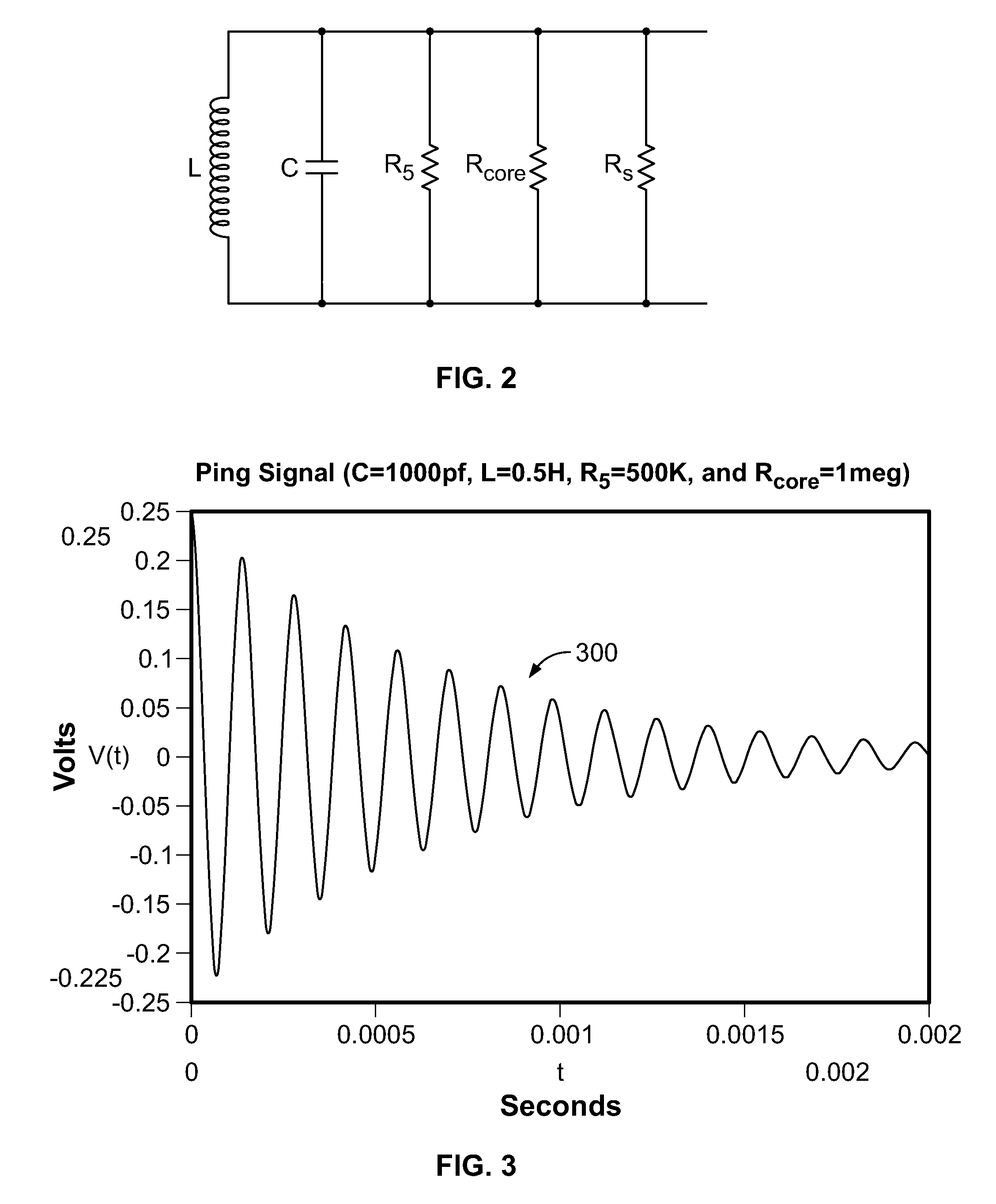
[0017]FIG. 1 illustrates a functional block diagram of a load-current detection circuit 100 that includes a resonant circuit 102 operatively coupled to a microcontroller 120. The resonant circuit 102 forms a parallel RLC circuit having resistive, inductive, and capacitive components, as modeled in FIG. 2. The capacitive component is supplied by the total parallel capacitance in the circuit 100, including C10, and the inductive component represents the inductance associated with a ground fault sensing transformer 104 having a conventional primary loop comprising a toroid ferrite core and a secondary winding 103. At least two non-concentric load conductors (line and neutral) 106, 108 pass through the central opening of the sensing transformer 104 (see FIG. 5). The resistive component of the resonant circuit 102 includes a known resistance of a resistor R5, connected in parallel with the capacitor C10, a resistive loss associated with the ferrite core of the sensing transformer 104, re...


PUM


Abstract

A circuit that includes a single grounded fault sensing transformer coupled to a resonant circuit that produces an output signal used by a microcontroller to determine a load current flowing through at least two conductors passing through the center of the sensing transformer. The microcontroller pings the resonant circuit, causing an impulse disturbance at the output signal, and the microcontroller calculates the inductance component of the resonant circuit based on the frequency of the decaying output signal. The microcontroller calculates the resistive core loss as a function of a known resistance of the resonant circuit, a known capacitance of the resonant circuit, the calculated inductance, and the determined rate of decay of the output signal. The calculated resistive core loss is compared to a table or to a polynomial function that characterizes known resistive core losses with known load currents to determine the load current corresponding to the calculated resistive core loss.

Description

FIELD OF THE INVENTION[0001]Aspects disclosed herein relate generally to current sensors, and, more particularly, to a method for measuring load current using a ground fault sensing transformer.BACKGROUND[0002]Measuring load current consumed by a load connected to a circuit is useful for metering analysis. One way to measure accurately a range of load currents is to couple a current sensor (typically a current transformer) to a conductor carrying the load current, and convert the sensor output into a representation of the load current. Current transformers are bulky as they are shaped like a toroid and are positioned so that the load conductor passes through an opening in the toroid-shaped core. A ground fault detector already includes a ground fault sensing transformer, so to measure load current, a second transformer is needed. Eliminating the need for a bulky second current transformer would be beneficial. In addition, load shifts caused by variations in the windings of the groun...

Claims


Application Information

Patent Timeline
Patent Type & Authority Patents(United States)
IPC IPC(8): H02H3/00G01R33/14
CPCG01R19/0092G01R31/025G01R31/52
Inventor REID, PAUL A.ERGER, ROBERT
Owner SCHNEIDER ELECTRIC USA INC
Why Eureka
Try Eureka