Method and apparatus for thermographic nondestructive evaluation of an object

Active Publication Date: 2011-11-08
GENERAL ELECTRIC CO
View PDF7 Cites 18 Cited by
  • Summary
  • Abstract
  • Description
  • Claims
  • Application Information

AI Technical Summary

Benefits of technology

[0008]According to another aspect, a method for determining thickness and depth of flaws in the object is provided. The method includes applying through-transmission mode imaging to the object and obtaining a through-transmission image of the object. The method then determines individual diffusivity values at different points in the through-transmission image. The method further includes calculating a thickness value at each respective point from the different points using a respective individual diffusivity value. The method also includes determining one or more flaws in the object based on thickness values at the plurality of points in the through-transmission image. Finally, the method includes using reflection mode imaging for determining a depth value for the one or more flaws since in through-transmission such depth measurements are not possible. Thus, combining the dual modes of thermographic imaging permits a complete characterization of a component.

Problems solved by technology

Finally, the method includes using reflection mode imaging for determining a depth value for the one or more flaws since in through-transmission such depth measurements are not possible.

Method used


Image

  • Method and apparatus for thermographic nondestructive evaluation of an object
  • Method and apparatus for thermographic nondestructive evaluation of an object
  • Method and apparatus for thermographic nondestructive evaluation of an object

Examples


Embodiment Construction

[0016]The different embodiments described herein relate to nondestructive testing methods and system for determining thickness and depth of flaws in an object using high-speed IR transient thermography, particularly using the through-transmission mode and reflection mode imaging techniques.

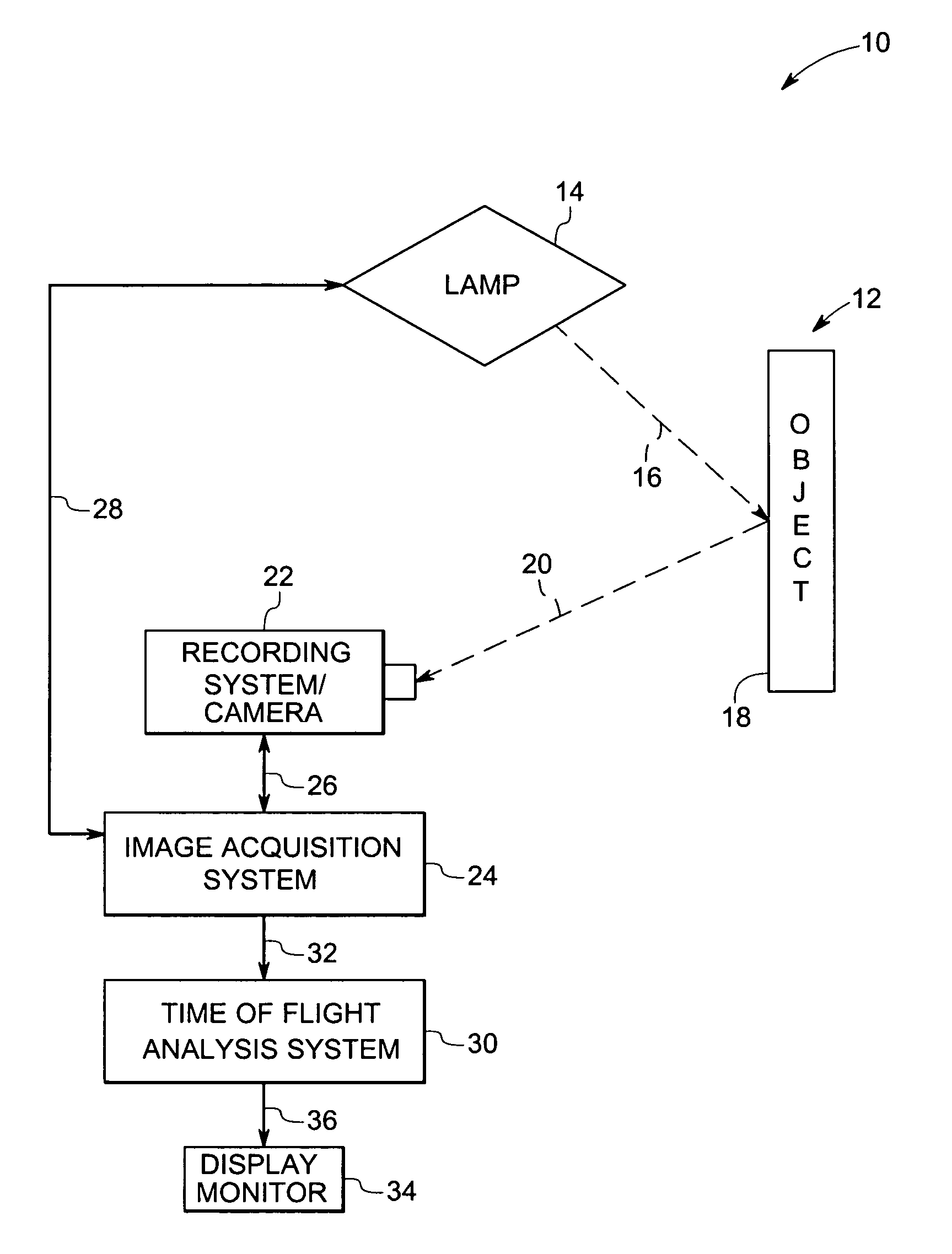
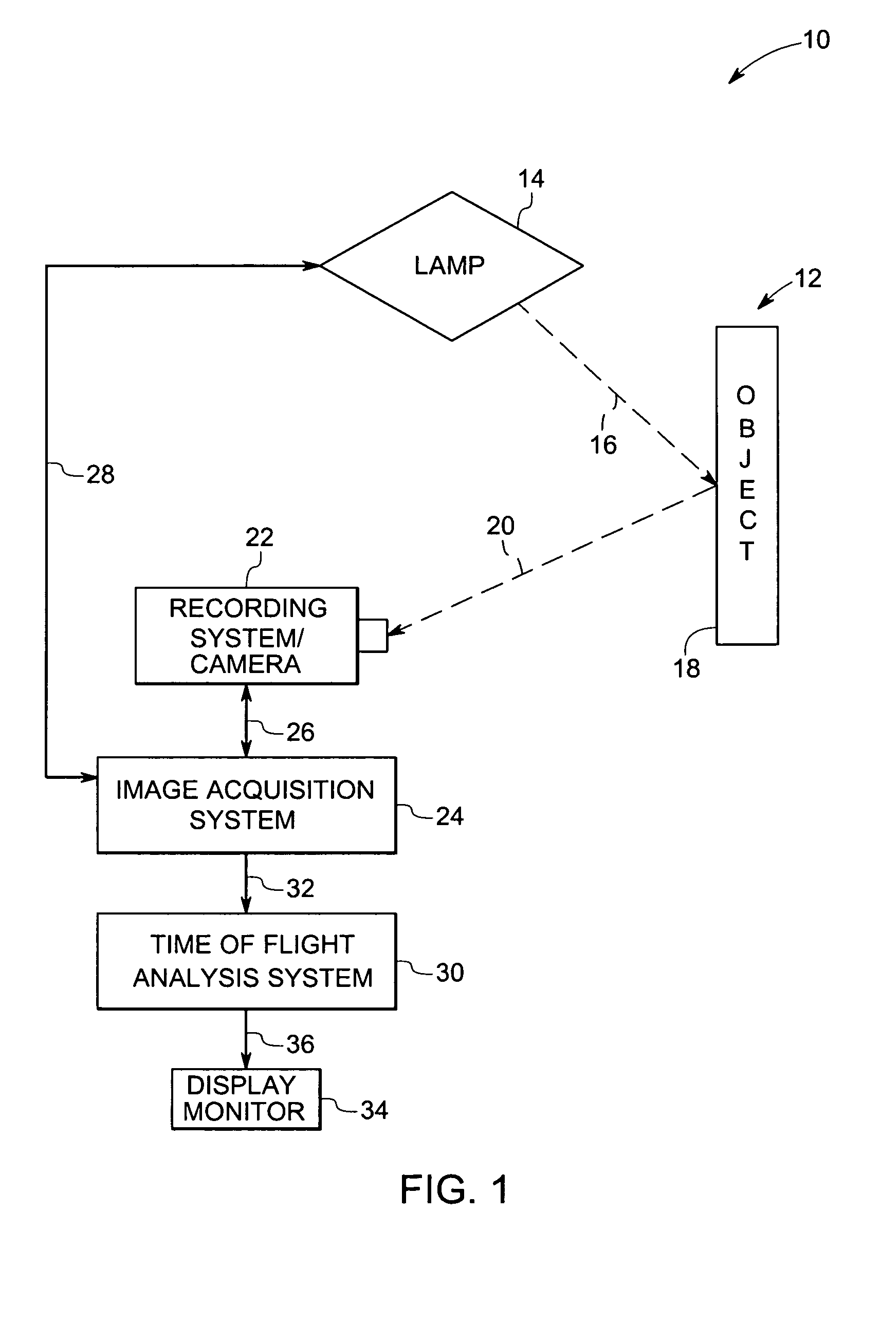
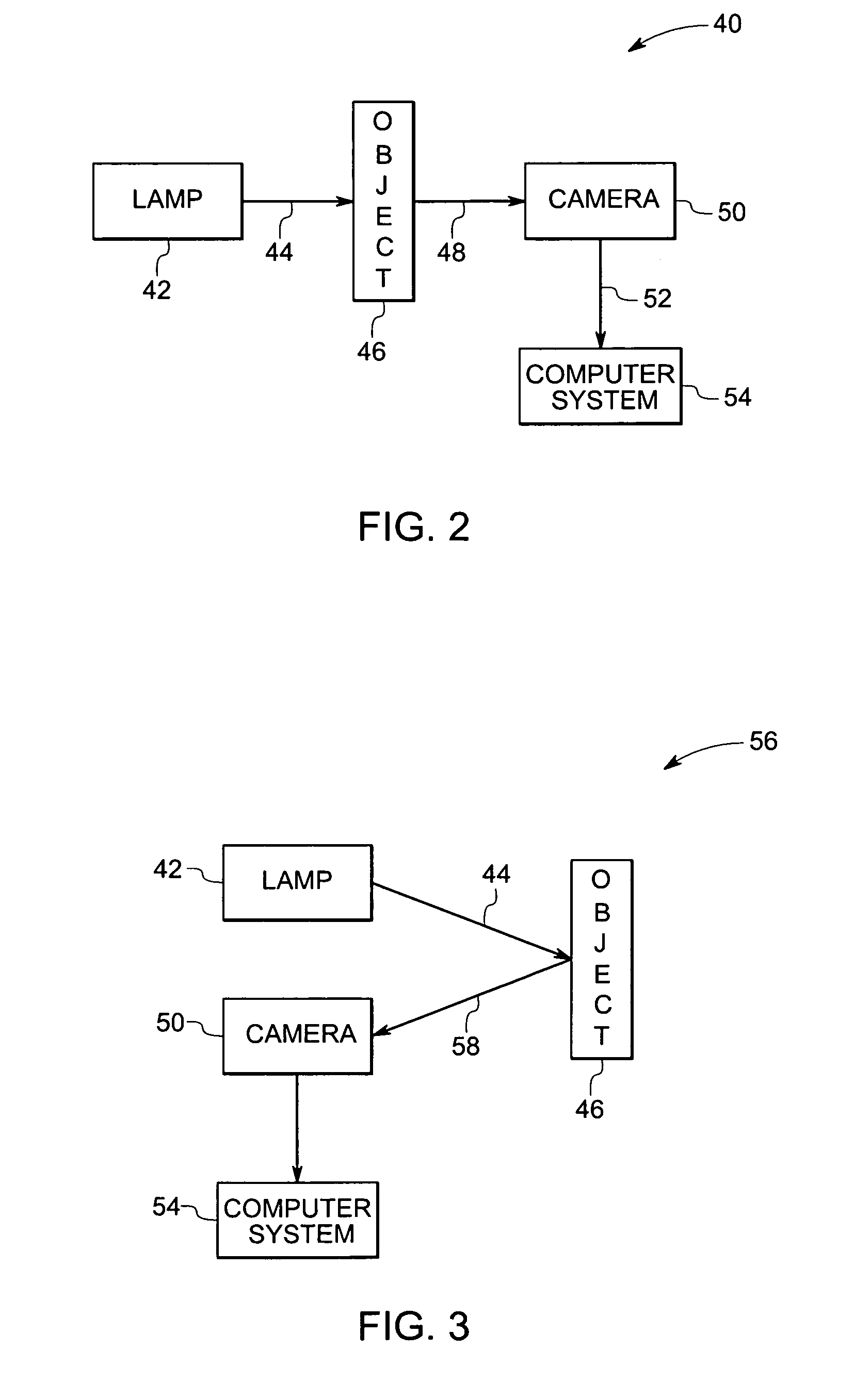
[0017]FIG. 1 shows a diagrammatic representation of a non-destructive evaluation system 10 for detecting flaws in a part or an object 12. The object 12 may be an industrial part, for example, a blade (turbine blade), a vane made of ceramics, combustion liner, a shroud or a similar part, for example for turbines or aircraft components. The system 10 includes a lamp 14 (for example, a flash lamp) for rapidly applying multiple high power optical pulses 16 on a surface 18 of the object 12. In one example, the lamp 14 is a linear lamp. In an exemplary embodiment, the lamp is configured to be moved for at least one of reflection mode imaging and through-transmission imaging. Two suitable arrangements fo...


PUM

PropertyMeasurementUnit
thermal cameraaaaaaaaaaa
time of flight analysisaaaaaaaaaa
time-temperatureaaaaaaaaaa

Abstract

A non-destructive evaluation system and method is provided for detecting flaws in an object. The system includes a lamp for impinging the object with optical pulses and a focal plane array camera configured to capture the images corresponding to evolution of heat due to an impact of the optical pulses in the object. The system also includes an image acquisition system for capturing data corresponding to the images from the focal plane array camera. Both transmission mode imaging and reflection mode imaging techniques are used in an exemplary embodiment. A time of flight analysis system is also provided for analyzing the data from both transmission mode imaging technique and reflection mode imaging technique. The data from transmission mode imaging is used to determine thickness values at different points in the data and for determining location of flaws using the thickness values. The data from reflection mode imaging is used for determining depth of these flaws.

Description

BACKGROUND[0001]The invention relates generally to a thermographic nondestructive testing technique for determining flaws in an object by determining thickness and diffusivity at different points on the surface of the object.[0002]Over the years, various nondestructive ultrasonic measurement techniques have been utilized to determine cross-sectional thickness of cast metal and other solid objects. Conventionally, the object is probed with ultrasonic waves, which penetrate the surface and are reflected internally at the opposite side or surface of the object. Based upon the time required to receive a reflected wave, the distance to the opposite (back) side can be determined, giving the thickness of the object at that point. Unfortunately, conducting ultrasonic measurements of this sort to examine the cross-sectional thickness would usually necessitate a cumbersome and time-consuming mechanical scanning of the entire surface with a transducer. In addition, to facilitate intimate sonic...

Claims


Application Information

Patent Timeline
Patent Type & Authority Patents(United States)
IPC IPC(8): G06K9/00G01N25/02G01N25/00G01N25/72G01J5/00G03G5/10G01K17/00G01K11/30G01T1/164G01T1/161G01T1/20G01J5/02
CPCG01B11/0608G01N25/72
Inventor RINGERMACHER, HARRY ISRAELHOWARD, DONALD ROBERTKNIGHT, BRYON EDWARD
Owner GENERAL ELECTRIC CO
Why Eureka
Try Eureka