Display brightness control circuit
a brightness control and display technology, applied in measurement devices, instruments, optical radiation measurement, etc., can solve the problems of lowering visibility insufficient light to be the basis of display image information,
- Summary
- Abstract
- Description
- Claims
- Application Information
AI Technical Summary
Benefits of technology
Problems solved by technology
Method used
Image

Examples
first embodiment
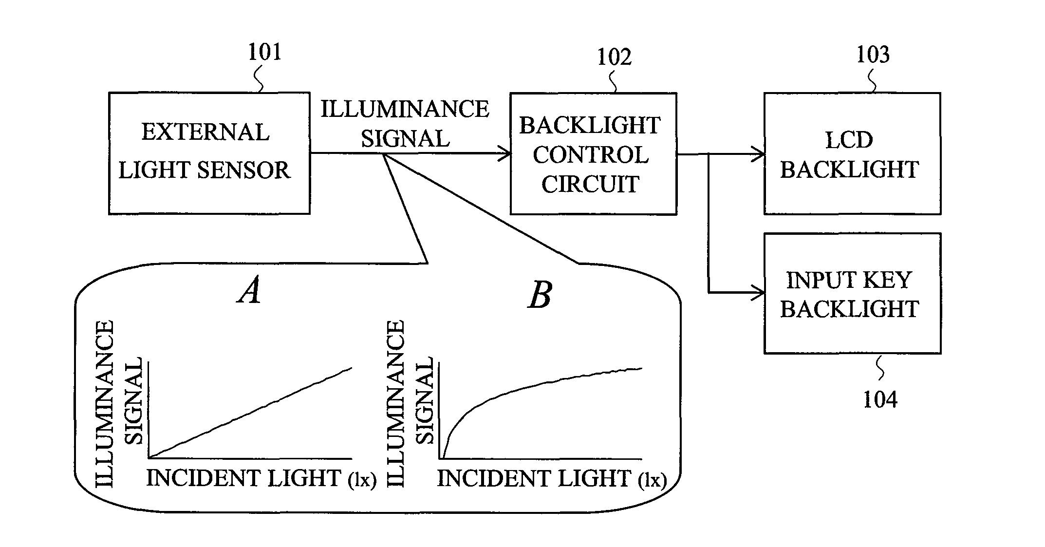
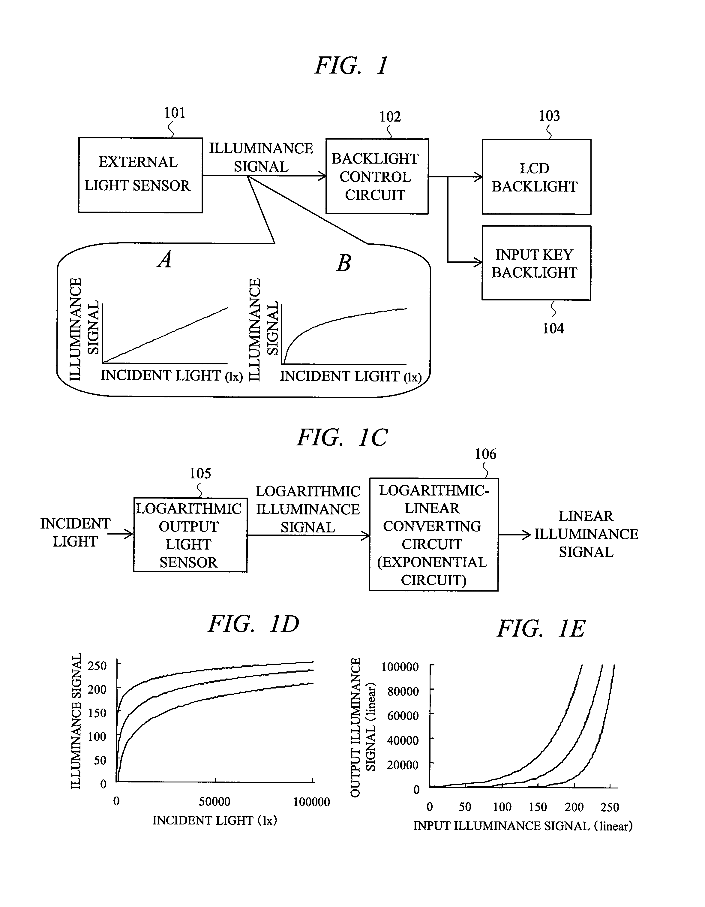
[0029]FIG. 1 is an explanatory diagram showing a principal part of a display device including a display brightness control circuit in a first embodiment of the present invention. In FIG. 1, a reference numeral 101 denotes an external light sensor, 102 denotes a backlight control circuit, 103 denotes an LCD backlight, 104 denotes an input key backlight, 105 denotes a logarithmic output light sensor, and 106 denotes a logarithmic-linear converting circuit. A display device in the present embodiment is an example of being applied to a liquid crystal display device and has a configuration in which the logarithmic output light sensor 105 is included in the external light sensor 101 and the logarithmic-linear converting circuit 106 for converting an illuminance signal having a logarithmic relationship with incident light into a linear signal is connected to an input stage of the backlight control circuit 102.
[0030]In the liquid crystal display device of the present embodiment, the externa...
second embodiment
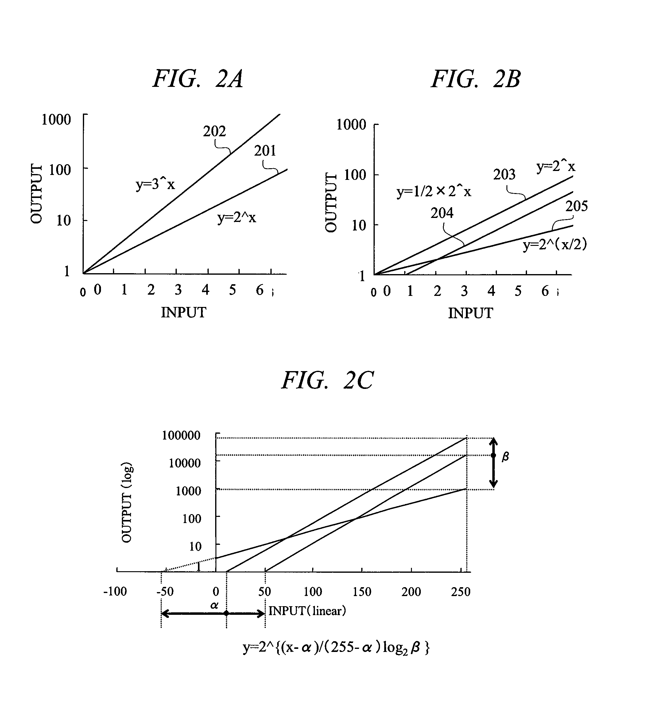
[0043]FIG. 5 is a diagram showing a graph obtained by replacing the graph of Equation 2 (FIG. 2C) described above in a liquid crystal display device including a display brightness control circuit in a second embodiment of the present invention. Though Equation 2 is led by setting the maximum value of an input signal x of the logarithmic-linear converting circuit to 255, if a range of an output signal is fixed and a width of the output signal is set to 16 bits, the maximum value becomes 2^16, and Equation 4 can be led.
y=2^{(x−α) / (255−α)×16} Equation 4
[0044]The graph of Equation 4 is shown in FIG. 5, in which a parameter determining a function is α only and all functions become straight lines inevitably passing through a point of (x,y)=(255, 2^16). This means that the maximum value of an input x inevitably corresponds to the maximum value of an output y of 2^16.
[0045]As described above, in the present embodiment, since an exponential is adjusted only by setting one parameter to the α...
third embodiment
[0046]FIG. 6 is an explanatory diagram showing a principal part of a display device including a display brightness control circuit in a third embodiment of the present invention. The display device in the present embodiment is applied to an organic EL display device, and the example where the display brightness control circuit is installed in an organic EL display will be described. In FIG. 6, a reference numeral 101 denotes an external light sensor including a logarithmic output light sensor 105, 501 denotes an organic EL power supply control circuit, 502 denotes an organic EL power supply circuit, and 503 denotes an organic EL panel.
[0047]In the organic EL display device of the present embodiment, the external light sensor 101 transmits an illuminance signal, the organic EL power supply control circuit 501 receives the illuminance signal and determines brightness of the organic EL display suitable for the brightness of external light, and the organic EL power supply circuit 502 co...
PUM
 Abstract
Description
Claims
Application Information
 - R&D
- Intellectual Property
- Life Sciences
- Materials
- Tech Scout
- Unparalleled Data Quality
- Higher Quality Content
- 60% Fewer Hallucinations
Browse by: Latest US Patents, China's latest patents, Technical Efficacy Thesaurus, Application Domain, Technology Topic, Popular Technical Reports.
© 2025 PatSnap. All rights reserved.Legal|Privacy policy|Modern Slavery Act Transparency Statement|Sitemap|About US| Contact US: help@patsnap.com