
Vision system for deploying safety systems

a safety system and vision system technology, applied in the direction of pedestrian/occupant safety arrangement, process and machine control, instruments, etc., can solve the problems of significant motor vehicle fatalities annually, inadvertent deployment of safety systems not only costly, and the height of bumpers remains the same. , to achieve the effect of slowing down the rate, and reducing the potential of injury

Active Publication Date: 2011-11-15
ARRIVER SOFTWARE LLC (N D GES D STAATES DELAWARE)
View PDF34 Cites 3 Cited by
  • Summary
  • Abstract
  • Description
  • Claims
  • Application Information

AI Technical Summary

Benefits of technology

The system effectively anticipates collisions, allowing for the deployment of safety devices at the optimal time, reducing the severity of impacts by providing advanced warning and enabling the use of larger airbags, seatbelt pre-tensioning, and structural modifications to enhance occupant safety.

Problems solved by technology

Collisions with bicyclists and pedestrians account for a significant number of motor vehicle fatalities annually.
While an effort has been made to match bumper heights for passenger cars, there remains a disparity between bumper heights, especially between classes of passenger vehicles, and especially involving collisions with heavy trucks.
Inadvertent deployment of safety systems is not only costly but may temporarily disable the vehicle.
Moreover, since the deployment of many safety systems is achieved through a release of energy, deployment at an inappropriate time may result in undesirable effects.
Although information obtained from radar systems yield valuable data, reliance upon a radar sensor signal for deploying a safety device may have certain negative consequences.
As mentioned previously, deployment of the external airbag is a significant event and should only occur when needed in an impending impact situation.
Radar sensor systems are, however, prone to “false-positive” indications.
However, a single imaging sensor provides only two-dimensional position information about approaching objects.
Certain aspects can be inferred about the travel of the object outside of the two-dimensional position, for example by determining a change is size of the object over a time period, but again this technique is not reliable enough for determining the deployment of a safety system.
In a case where the contact based side airbag activation might trigger late in the crash, there is potential for the occupant to be displaced laterally before the airbag is triggered.
Such displacement prior to activation reduces the effectiveness of the side airbag.

Method used


Image

  • Vision system for deploying safety systems
  • Vision system for deploying safety systems
  • Vision system for deploying safety systems

Examples


Embodiment Construction

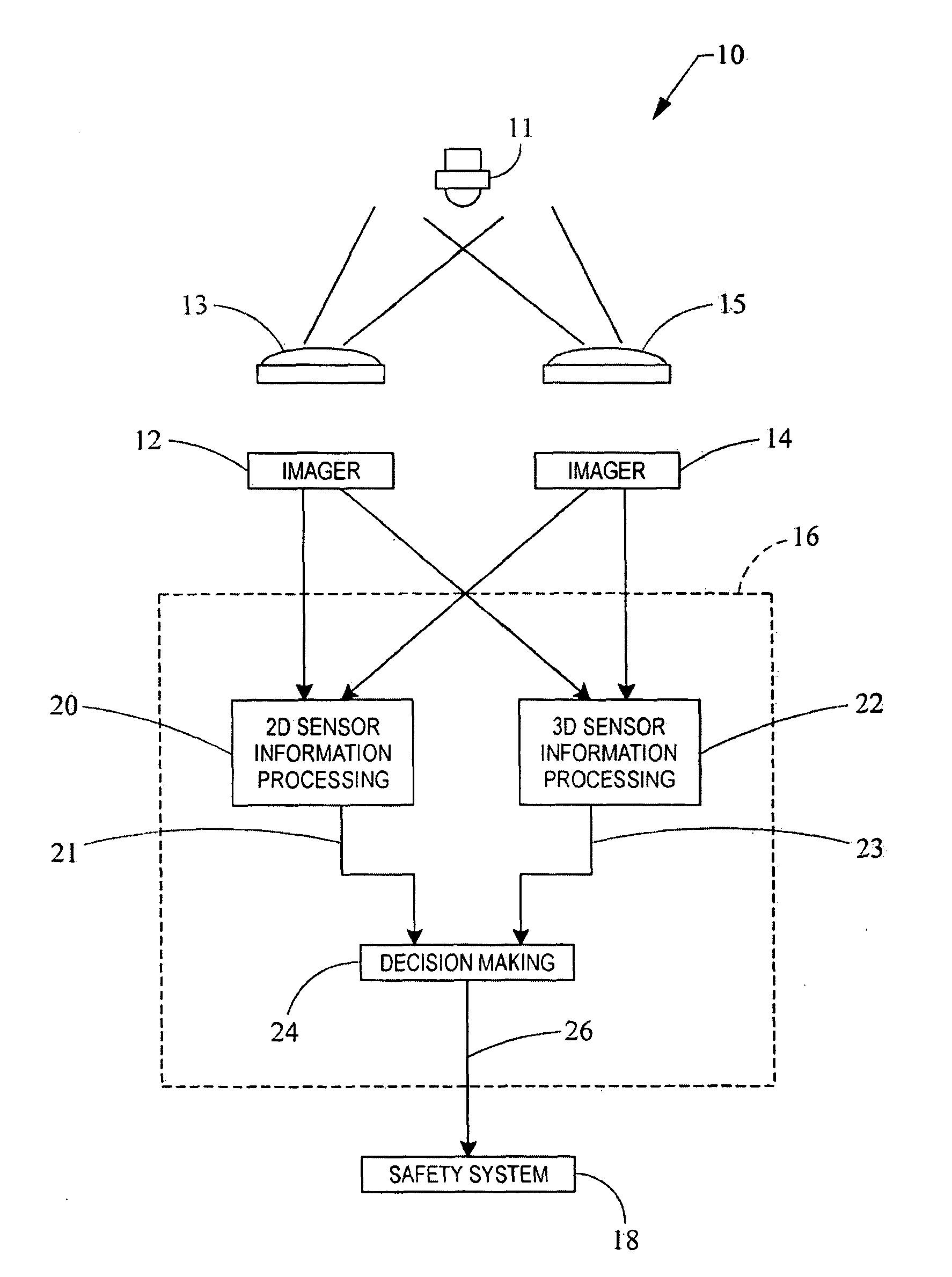
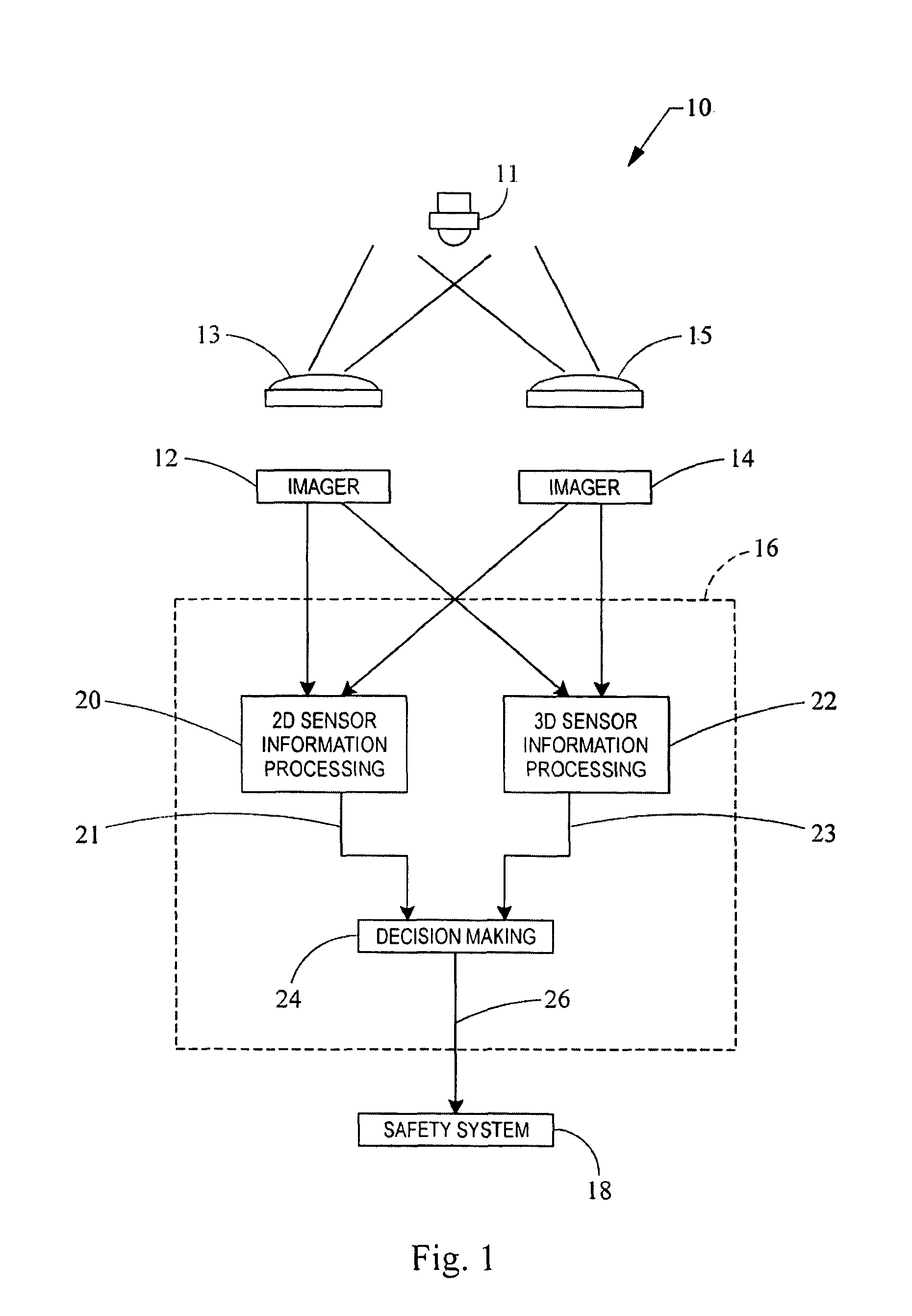
[0015]Referring now to FIG. 1, a system embodying the principles of the present invention is illustrated therein and designated at 10. The system 10 includes a first imager 12, a second imager 14, and a processor 16.

[0016]The first imager 12 and the second imager 14 are configured in a spaced relationship to view an object 11. The first imager 12 has a lens system 13 that is configured to view an object from a first direction. The second imager 14 includes a second lens system 15 configured to view the object 11 from a second direction. Since the first imager 12 and second imager 14 produce images of the object from different directions, the object may have a different apparent location between the first imager 12 and second imager 14.

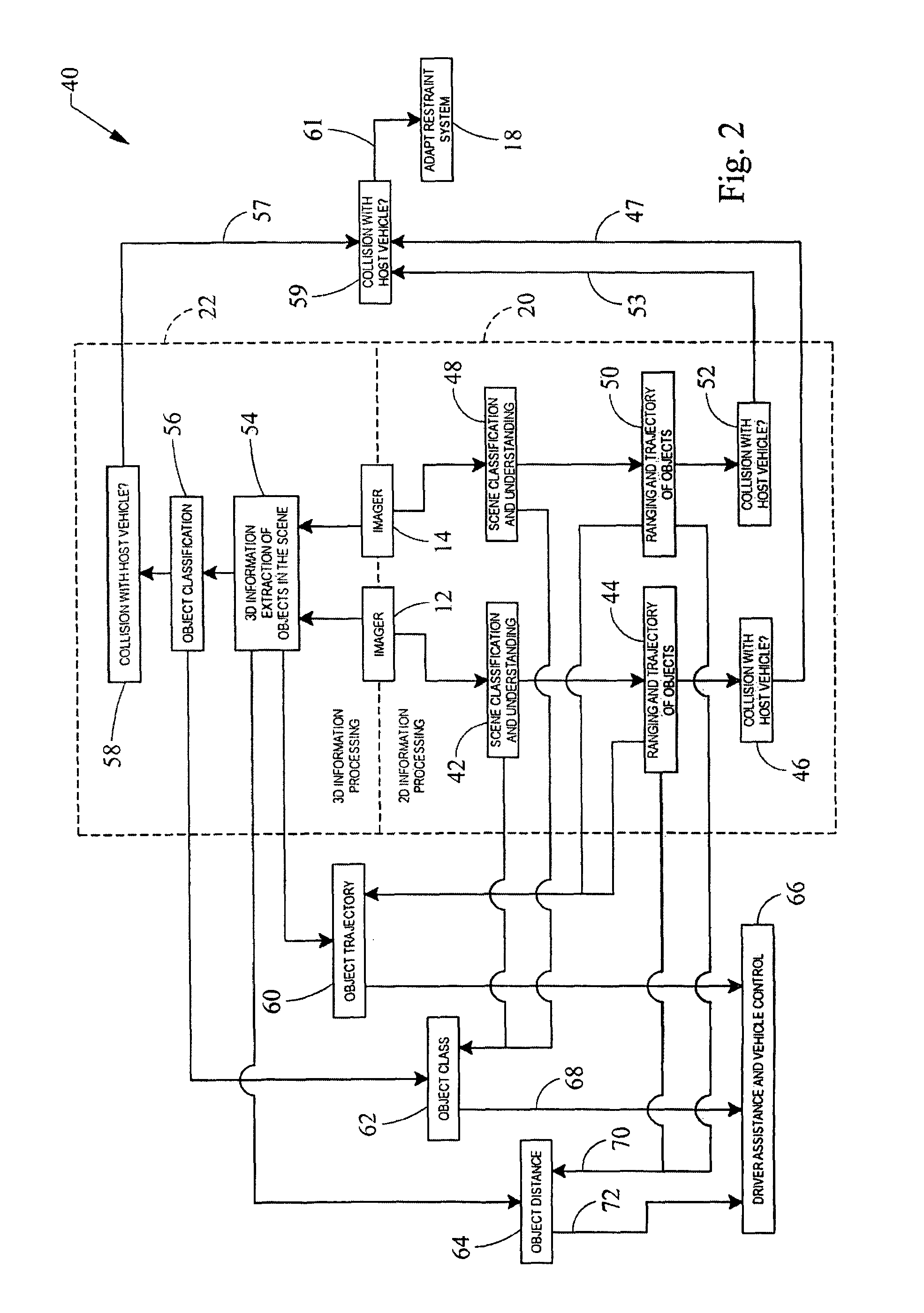
[0017]The two-dimensional images from the first and second imager 12, 14, are provided to a two-dimensional information processing algorithm 20 in processor 16. The two-dimensional information from each imager 12, 14 may be used independently. For exam...


PUM


Abstract

A control system for safety deployment. The control system includes a processor, a first imaging sensor, and a second imaging sensor. The first and second imaging sensor are in electrical communication with the processor. The processor generates a safety system activation decision based on two-dimensional information received from the first imaging sensor and three-dimensional information based on the first and second imaging sensor.

Description

FIELD OF THE INVENTION[0001]This invention relates to a system for sensing a motor vehicle impact and the deployment of a safety device.BACKGROUND AND SUMMARY OF THE INVENTION[0002]Enhancements in automotive safety systems over the past several decades have provided dramatic improvements in vehicle occupant protection. Presently available motor vehicles include an array of such systems, including inflatable restraint systems for protection of occupants from frontal impacts, side impacts, and roll-over conditions. Advancements in restraint belts and vehicle interior energy absorbing systems have also contributed to enhancements in safety. Many of these systems must be deployed or actuated in a non-reversible manner upon the detection of a vehicle impact to provide their beneficial effect. Many designs for such sensors are presently used to detect the presence of an impact or roll-over condition as it occurs.[0003]In addition, attention has been directed recently to providing deployab...

Claims


Application Information

Patent Timeline
Patent Type & Authority Patents(United States)
IPC IPC(8): B60R22/00
CPCB60R21/0134B60R2021/0002
Inventor HADI, SALAHDECKER, STEPHEN
Owner ARRIVER SOFTWARE LLC (N D GES D STAATES DELAWARE)
Learn More