Collecting part structure of exhaust manifold

a technology of exhaust manifold and collecting part, which is applied in the direction of combustion engines, machines/engines, mechanical equipment, etc., can solve the problems of deteriorating collecting part, inability to meet the requirements of conventional exhaust manifold, so as to achieve the effect of reducing the concentration of heat stress and improving the assembly performance of partition plate 10 and collecting part 6

Inactive Publication Date: 2011-11-22
CALSONIC KANSEI CORP
View PDF12 Cites 16 Cited by
  • Summary
  • Abstract
  • Description
  • Claims
  • Application Information

AI Technical Summary

Benefits of technology

[0010]The collecting part structure of the exhaust manifold includes the plurality of branch pipes, the collecting part, the partition plate and the sensor attachment boss part. The branch pipes have the exhaust-gas upstream side end portions that are connected with the head flange. The collecting part collects and contains the exhaust-gas downstream side end portions of the branch pipes. The partition plate has the exhaust-gas upstream side end portion is fixed among the exhaust-gas downstream side end portions of the branch portions, and the partition plate is arranged in the state where the exhaust-gas downstream side end portion of the partition plate projects in the interior of the collecting part. The sensor attachment boss part is fixed by welding on the portion of an outer circumferential portion of the collecting part in the state where the sensor attachment boss part faces the attachment hole formed in the collecting part. The plurality of insertion holes are formed in the reduced diameter portion of the collecting part. The partition plate is fixed by welding on the portion of the outer circumferential portion of the collecting part in the state where portions of the partition plate are inserted in and positioned to the insertion holes.
[0011]Therefore, the assembly performance of the partition plate 10 and the collecting part 6 can be improved. In addition, the concentration of the heat stress can be eased in the welding process.

Problems solved by technology

The conventional exhaust manifolds, however, have the following problems.
As a result, the partition plate could not be inserted through the slit from above, and an assembly performance of the partition plate and the collecting part sometimes deteriorates.
Further, there is another problem in that a heat stress concentrates on a cross portion of a first welding line that is formed when the partition plate is welded along the slit, and a second welding line that is formed when the branch pipes are welded along an entire circumference of the exhaust-gas upstream side end portion of the collecting part.
Incidentally, it is difficult for practical purposes to fix the sensor attachment boss part on the collecting part by welding in latter process because of a small space for welding work.

Method used


Image

  • Collecting part structure of exhaust manifold
  • Collecting part structure of exhaust manifold
  • Collecting part structure of exhaust manifold

Examples


first embodiment

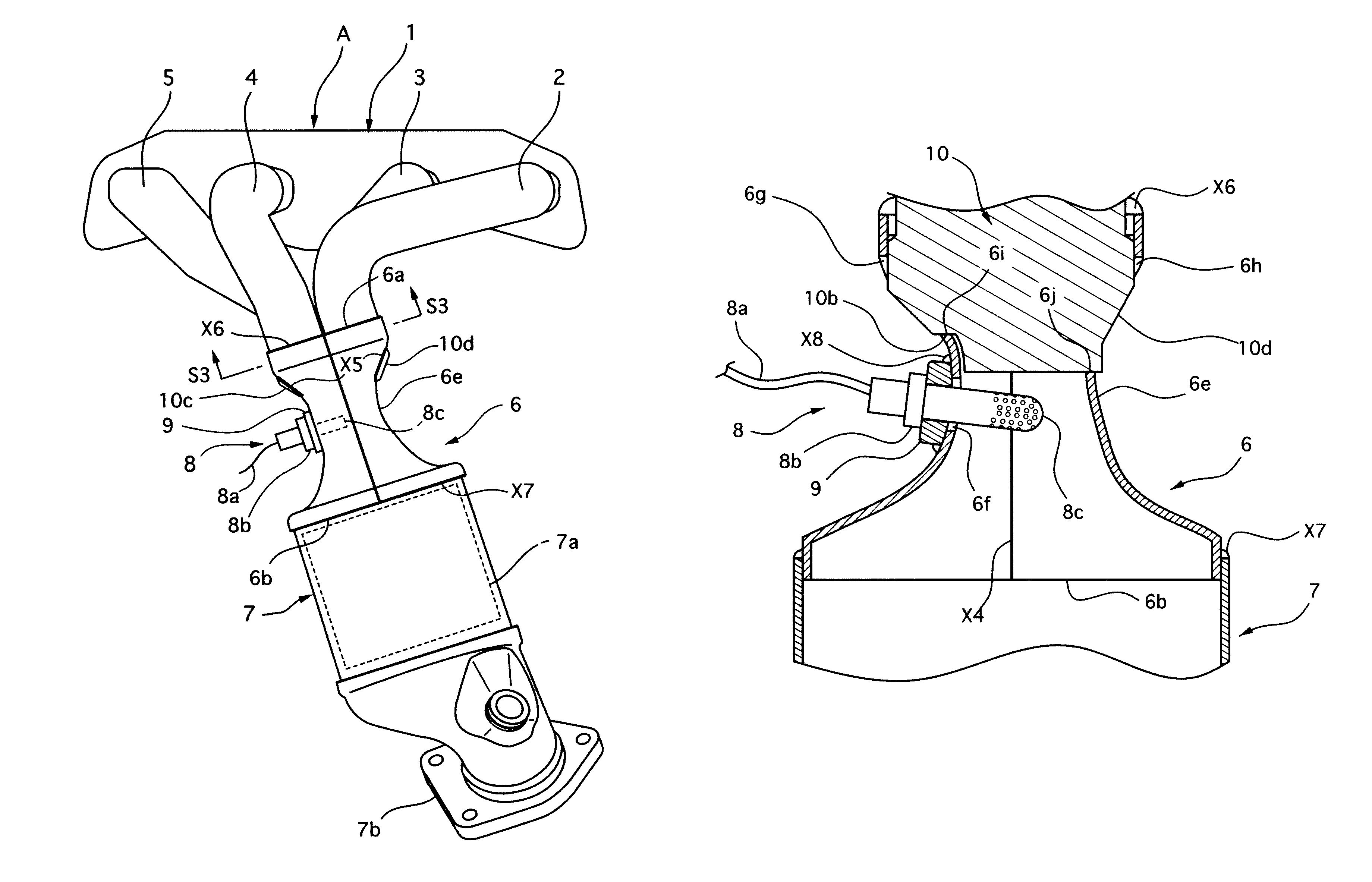
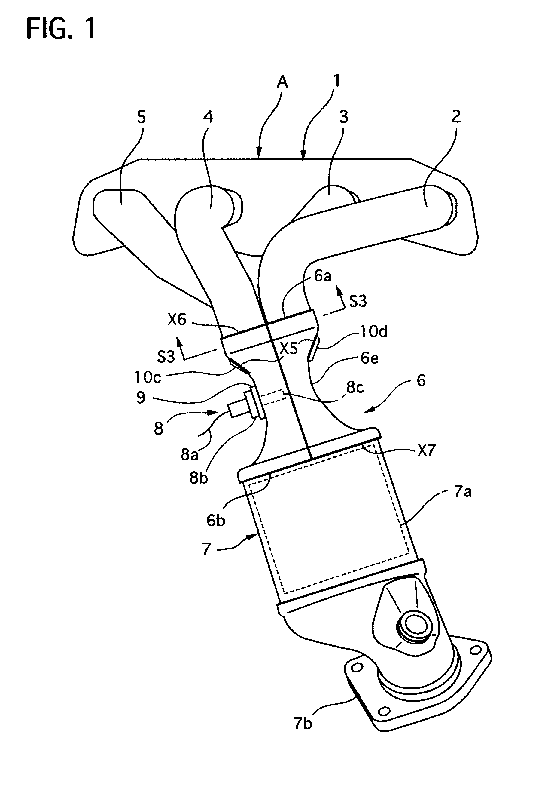
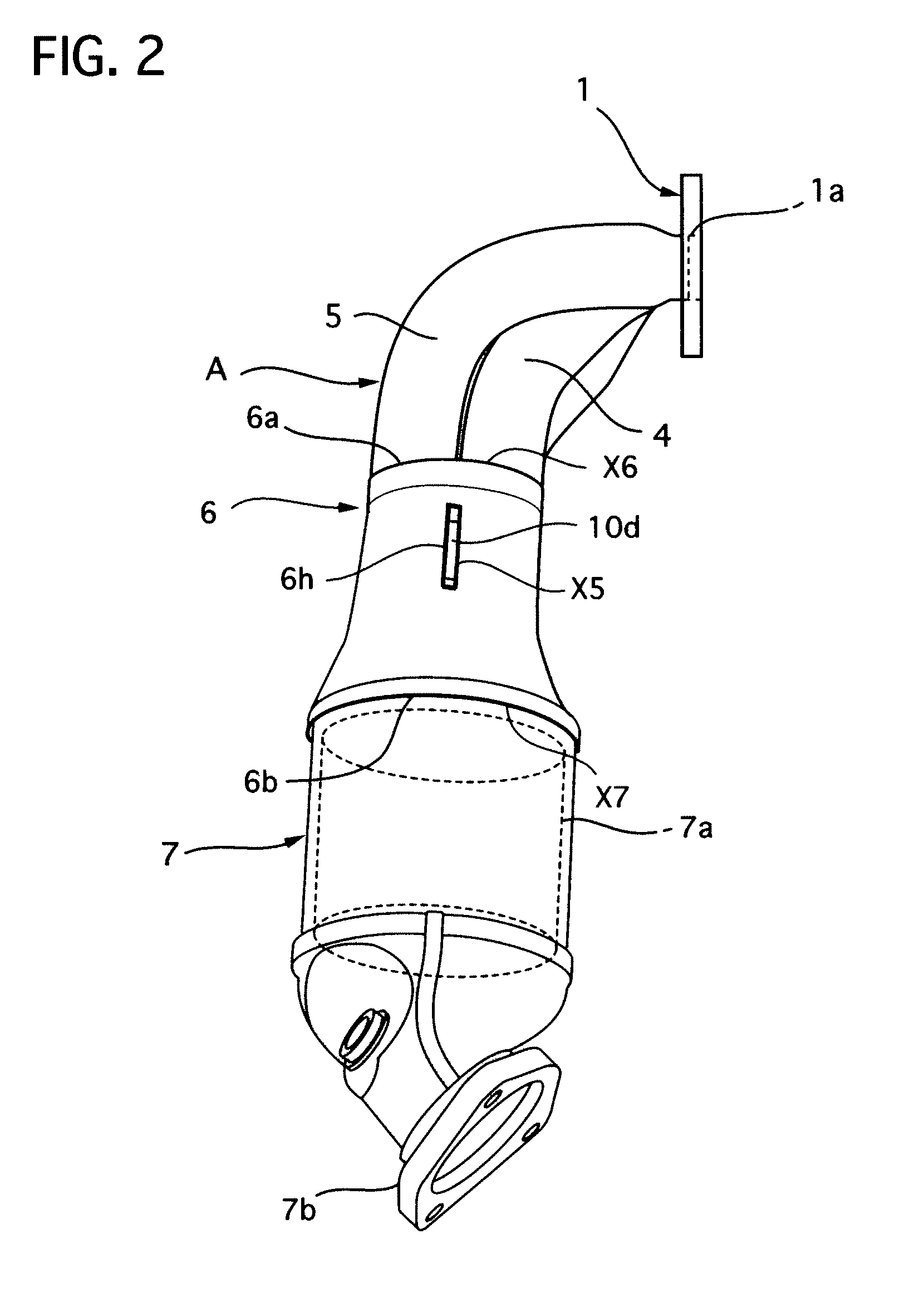
[0053]A first embodiment of the present invention will be described. FIG. 1 is a front view showing an exhaust manifold of the first embodiment according to the present invention, FIG. 2 is a right side view showing the same, FIG. 3 is a cross sectional view of the same taken along a line S3-S3 in FIG. 1, and FIG. 4 is a perspective view illustrating a partition plate of the first embodiment.

[0054]FIG. 5 is a front view showing a collecting part of the exhaust manifold of the first embodiment, FIG. 6 is a rear view showing the same, FIG. 7 is a right side view showing the same, FIG. 8 is a left side view showing the same, FIG. 9 is a cross sectional view of the same taken along a line S9-S9 in FIG. 8, FIG. 10 is a cross sectional view illustrating the collecting part of the first embodiment, and FIG. 11 is a view illustrating a fixation of the partition plate and the collecting part.

[0055]First, an entire construction of the exhaust manifold of the first embodiment will be described...


PUM


Abstract

An exhaust manifold A includes, in its collecting part structure, a plurality of branch pipes 2 to 5 that are connected with a flange head 1, a collecting part 6 that collects and contains exhaust-gas downstream side end portions 2a to 5a of the branch pipes 2 to 5, a partition plate 10 that is arranged in a state where its exhaust-gas downstream side end portion 10a projects in the interior of the collecting part 6, and a sensor attachment boss part 9 that is fixed by weld line X on a part of an outer circumferential portion of the collecting part 6 in a state where it faxes an insertion hole 6f formed in the collecting part 6. Insertion holes 6g and 6h are formed in a reduced diameter portion 6e of the collecting part 6 of the exhaust manifold A, and the partition plate 10 is fixed by a weld line X5 with a portion of the outer circumferential portion of the collecting part 6 in a state where portions 10c and 10d of both end portion of the partition plate 10 are inserted in and positioned to the insertion holes 6g and 6h.

Description

TECHNICAL FIELD[0001]The present invention relates to a collecting part structure of an exhaust manifold that constitutes a part of an exhaust system for discharging exhaust gas outputted from an engine mounted on a motor vehicle.BACKGROUND OF THE INVENTION[0002]A technology of a collecting part structure of an exhaust manifold is disclosed in Japanese Patent applications Publication No. 2004-245156 and No. 2004-116382, and they include a plurality of branch pipes, a collecting part, a partition plate and a sensor attachment boss part, where the branch pipes have exhaust-gas upstream side end portions that are connected with a head flange of an engine, the collecting part collects and contains exhaust-gas downstream side end portions of the branch pipes, the partition plate has an exhaust-gas upstream side end portion that is fixed among the exhaust-gas downstream side end portions of the branch pipes and an exhaust-gas downstream side end portion that is arranged to project in an i...

Claims


Application Information

Patent Timeline
Patent Type & Authority Patents(United States)
IPC IPC(8): F01N1/00F01N13/10F01N13/18
CPCF01N13/008F01N13/10F01N13/1838F01N13/1872F01N2450/22
Inventor SHIBASAKI, TAKASHI
Owner CALSONIC KANSEI CORP
Why Eureka
Try Eureka