Heated flowable product dispenser

a flowable product and dispenser technology, applied in the field of heat dispensing products, can solve the problems of limiting the consumer's ability to use the dispenser at a remote location, consuming unnecessary energy, and degrading the cream or lotion, and achieve the effect of reliable heat dispensing and low production cos

Inactive Publication Date: 2011-11-22
SC JOHNSON & SON INC
View PDF48 Cites 17 Cited by
  • Summary
  • Abstract
  • Description
  • Claims
  • Application Information

AI Technical Summary

Benefits of technology

[0027]Another form of the invention relates to a device for dispensing a heated flowable product. There is a docking station connectable to an electrical power source, a bottle having a flowable product stored therein, the bottle having a heater and means for driving the heated flowable product out of the bottle, and the bottle is removably engaged with the docking station with the bottle being inverted so that while its heater is positioned adjacent a downward end of the device the bottle can be activated by the docking base so that the bottle can heat a portion of the flowable product, and heated flowable product can be dispensed while the bottle is inverted and engaged with the docking station.
[0029]It will be appreciated from the above and the following description and the drawings that the present invention has a number of advantages. In addition to providing a heated lotion / cream dispenser that can be used at a counter top or alternatively at a remote site, the device is configured so that gravity facilitates dispensing at the base. Thus, less energy is needed to dispense the heated product, and there is less tendency for difficulty in dispensing the last remaining product in the container.
[0031]Additionally, the device reliably heats product without unnecessarily heating substantial product that is not likely to be quickly dispensed. Further, the device is relatively inexpensive to produce given the functions being provided.

Problems solved by technology

However, continuous heating of a main reservoir of cream or lotion risks degradation of the cream or lotion over time, and in any event uses unnecessary amounts of energy.
While such systems do have some utility, they limit the consumer's ability to use the dispenser at a location remote from the power supply.
For example, women may prefer to shave their legs in the shower and it is impractical to use such cord linked systems within a shower environment.
However, this system relied on an awkward pumping mechanism, and has certain other deficiencies.
Another concern with some prior art systems, particularly those relying on pumping or pressurized containers, is that even after a consumer has stopped activating the dispensing apparatus, because of residual pressure in the outlet area, and / or the expandable / foaming nature of the cream or lotion being delivered, the nozzle will have a tendency to “drool” during the next hour or so, leaving a somewhat unsightly appearance.
The drooled material will be exposed to air and therefore also degrade.
Still other systems are designed for delivering heated lotions, creams or other materials where the system has undesirably small capacity (e.g. certain aerosol systems), or is difficult to refill or provide replacement supply for.
In still other such devices the device requires extended warm-up time to cause a desired amount of cream or lotion to be heated to the desired temperature, or is designed in a way that if more than a relatively small amount of lotion or cream is dispensed within a short time period the device will begin to deliver insufficiently heated product.
In still other such devices the means of causing the delivery of the heated product when at a base station is awkward and / or inefficient and / or non-intuitive.
It is also of concern that these devices typically require the use of a human hand to work the cream or lotion into or against the skin.
Consumers may prefer not to use this manner of applying the cream or lotion, and / or for some purposes this manner of applying the product may not be optimal.

Method used


Image

  • Heated flowable product dispenser
  • Heated flowable product dispenser
  • Heated flowable product dispenser

Examples


Embodiment Construction

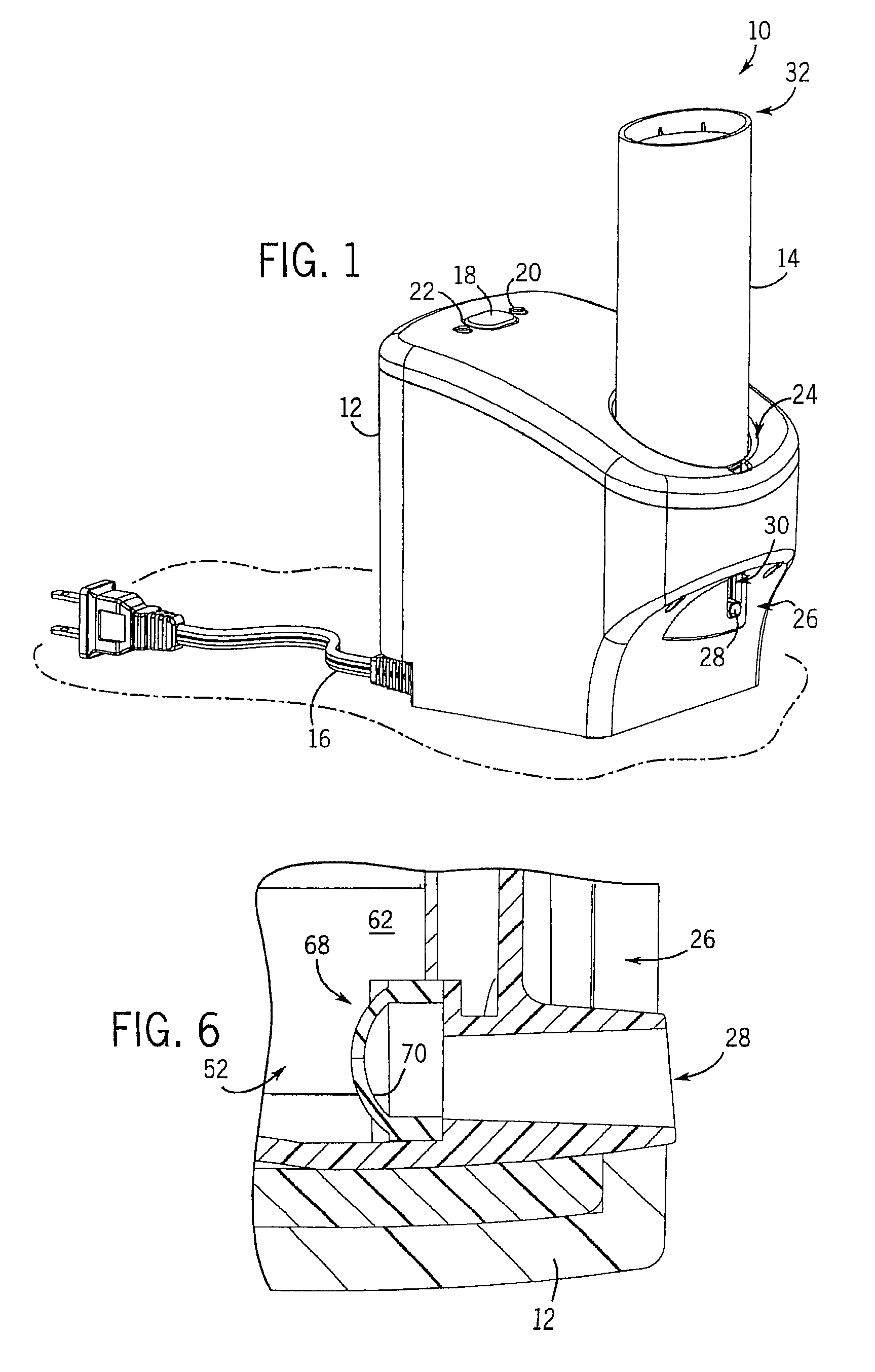
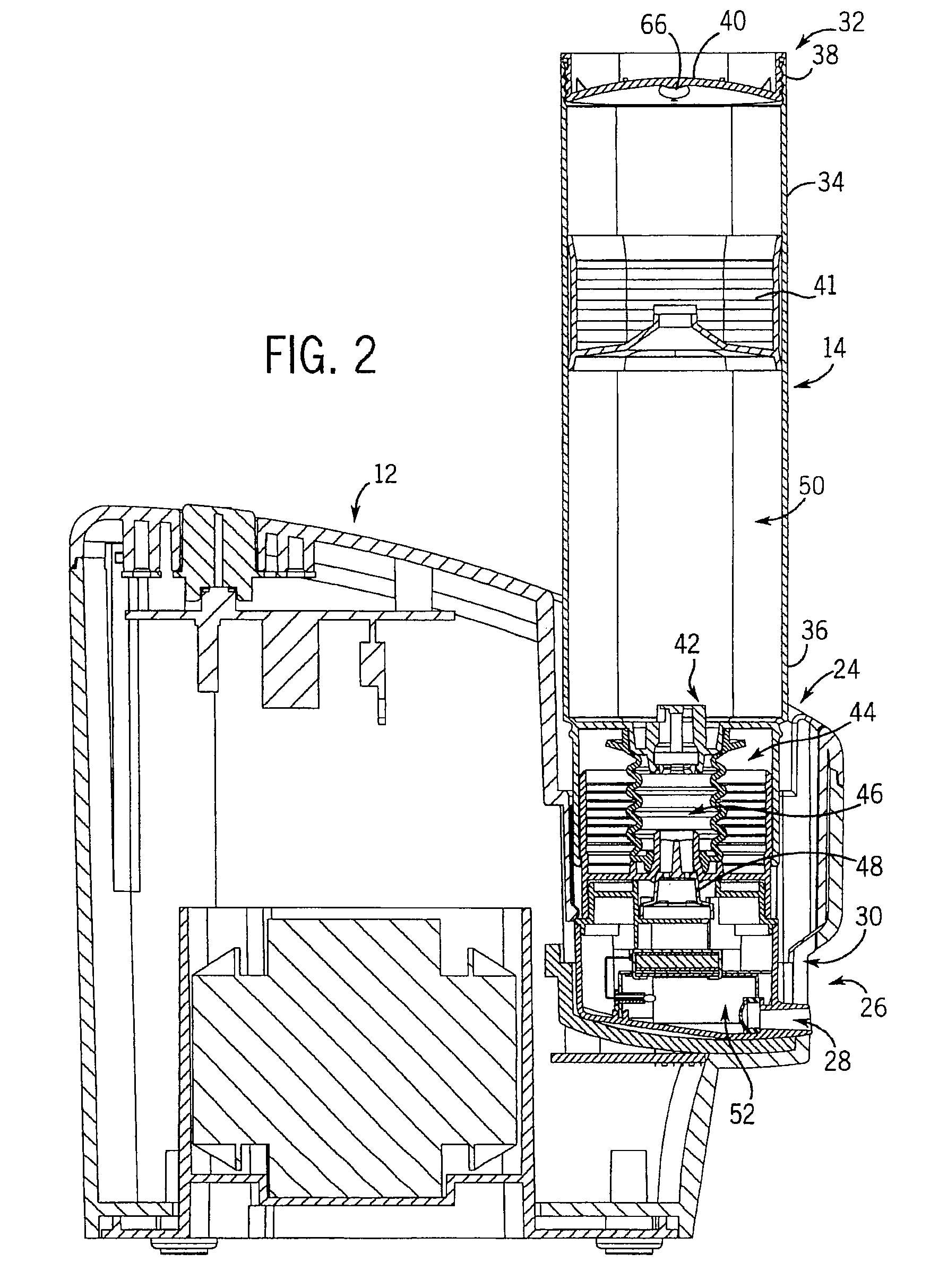
[0060]Referring to FIG. 1, a product dispensing device 10 includes a docking station 12 that receives a dispensing bottle 14 in an inverted arrangement. The docking station 12 includes a power cord 16 adapted to be received by a utility power receptacle (not shown) to deliver power to the docking station 12. The docking station 12 transmits the power received from the power cord 16 to the bottle 14 that, in turn, heats a portion of the product as it is delivered from a reservoir cavity of the bottle 14.

[0061]To turn the supply of power delivered from the docking station 12 to the bottle 14 on or off, a power switch 18 is provided. Additionally, the docking station includes a pair of indicator lights 20, 22 that are designed to indicate whether the docking station is currently delivering power that is consumed by the bottle 14 to heat a portion of the product or whether the docking station 12 is in a standby mode where no power is being delivered from the docking station 12. There ma...


PUM


Abstract

A bottle includes a product stored therein. It is configured to be removably engaged with a docking station in an inverted arrangement to be activated by the docking station and heat the product. The bottle may include a pump structure (e.g. in the form of a bellows), or be a squeezable bottle, or be a bowable bottle, or have other pumping features. Structures are provided to prevent drool after use, to help apply the heated product to the skin, and to insure proper heating and dispensing. Docking stations and bottles can be combined where the bottle is positioned in an inverted manner, and there can be methods for using these devices.

Description

CROSS-REFERENCE TO RELATED APPLICATIONS[0001]Priority is claimed based on U.S. provisional application 60 / 791,864 filed on Apr. 13, 2006.STATEMENT REGARDING FEDERALLY SPONSORED RESEARCH / DEVELOPMENT[0002]Not applicable.BACKGROUND OF THE INVENTION[0003]The present invention relates to devices for dispensing heated flowable products such as personal care products (e.g. heated shaving lotions and skin lotions), home cleaning products, or any other type of product that is desired to be heated and which can withstand an elevated temperature above an ambient temperature. More specifically it relates to such devices that have portable containers that can be energized by a base unit to heat products, as well as to structures that permit heated products to be dispensed from the container adjacent the base or alternatively remote there from.[0004]Certain personal care products, cleaners and other compositions are advantageously used in a heated condition. For example, many prefer to shave usin...

Claims


Application Information

Patent Timeline
Patent Type & Authority Patents(United States)
IPC IPC(8): A46B11/02B67D7/82
CPCA45D34/00A47K5/12B05B11/0002B05B11/3035B05B11/1035
Inventor SKALITZKY, MICHAEL J.LEONARD, STEPHEN B.HARWIG, JEFFREY L.SHIRLEY, STEVEN C.NORWOOD, RICHARD L.CHENG, FUK YUENWEN, ZHI BINSHI, JIANKOPANIC, ROBERT J.
Owner SC JOHNSON & SON INC
Why Eureka
Try Eureka