
Low thermal mass, adjustable locking GC nut

a technology of adjustable locking and gc nut, which is applied in the direction of ion-exchangers, instruments, separation processes, etc., can solve the problems of difficult to reach the installation inlet, and hot columns and fasteners, and achieve a small mechanical advantage, eliminating the need for wrench

Inactive Publication Date: 2011-11-22
PHENOMENEX INC
View PDF5 Cites 5 Cited by
  • Summary
  • Abstract
  • Description
  • Claims
  • Application Information

AI Technical Summary

Benefits of technology

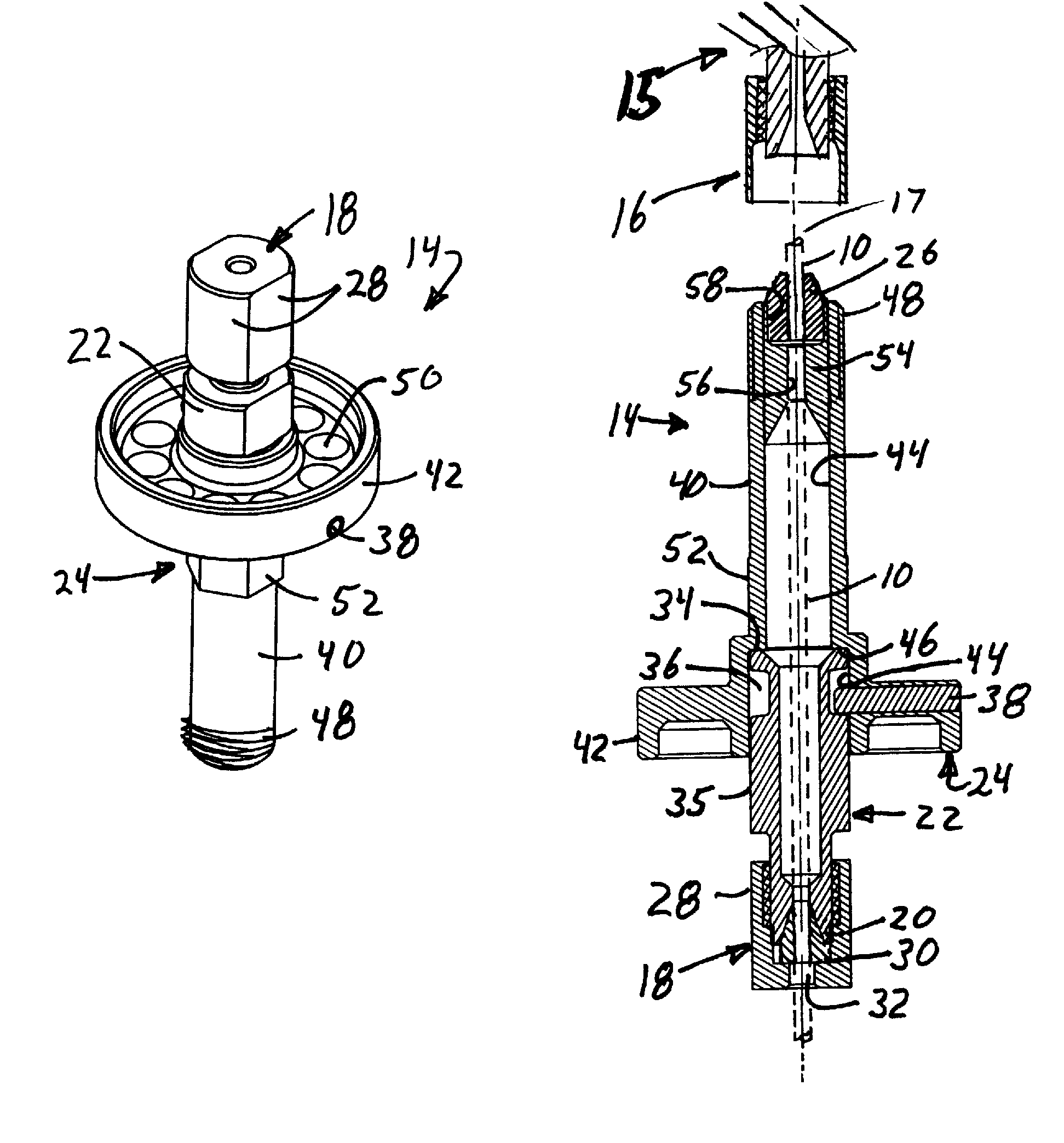
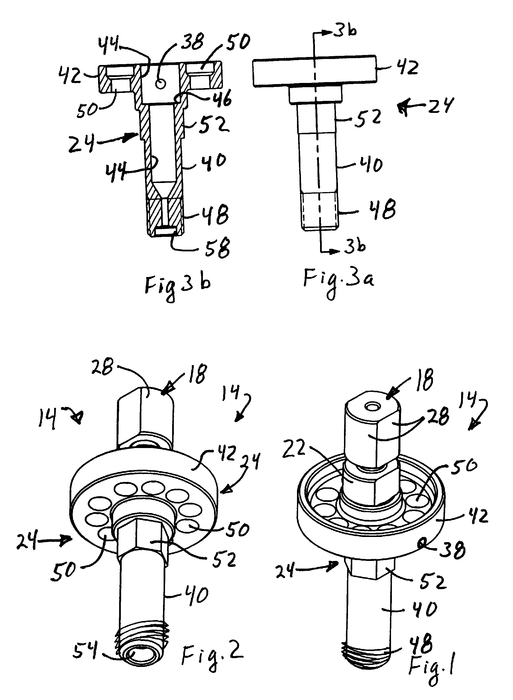
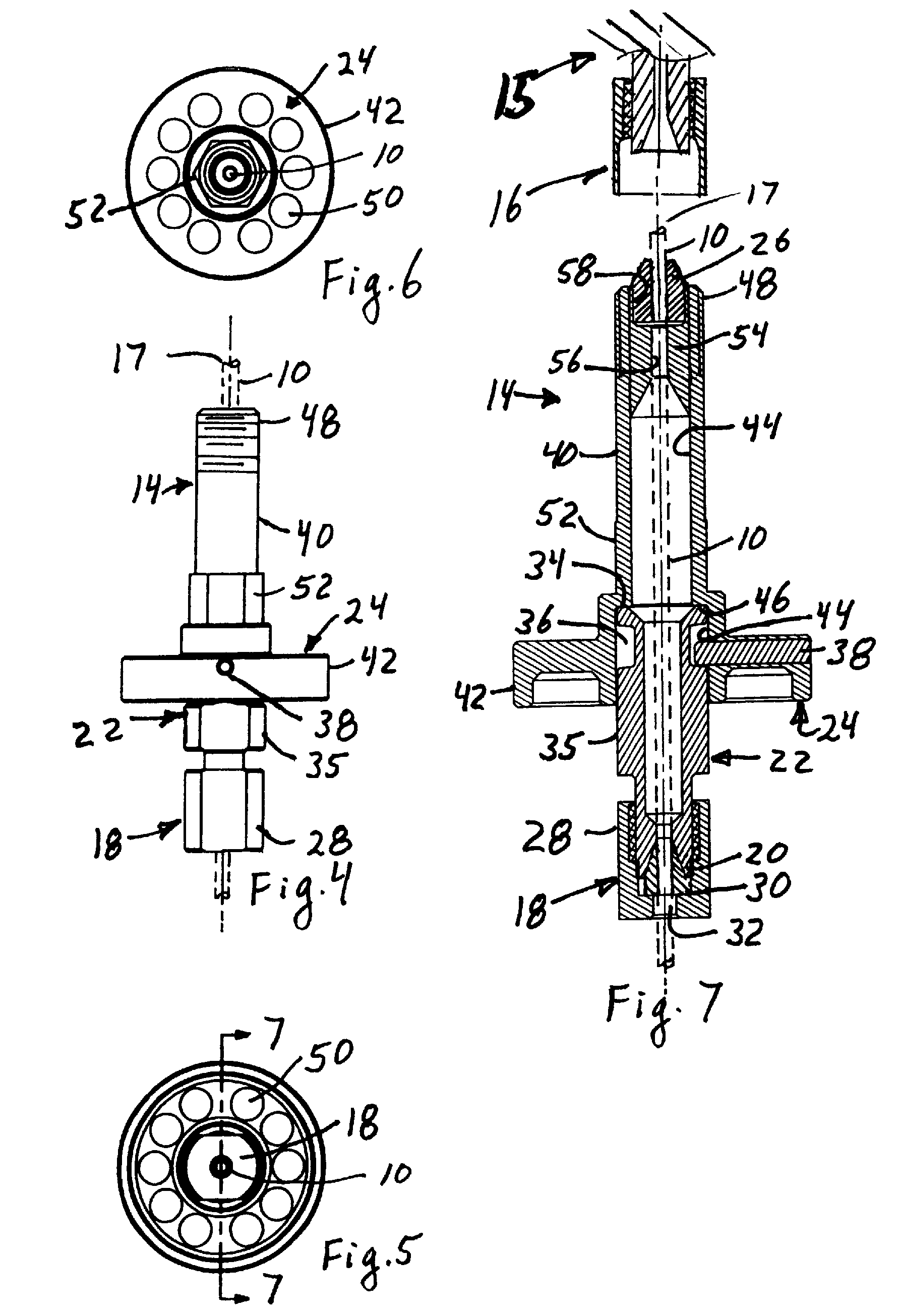
"The patent describes a connector for connecting a gas chromatography capillary column to chromatography equipment. The connector includes a securing body, a securing nut, and a main body. The securing body has a ferrule recess and an annular recess, and the main body has a ferrule recess and a part extending into the annular recess to limit motion of the securing body. The connector allows for easy and comfortable installation of the capillary column without the need for wrenches and ensures accurate and reproducible analysis."

Problems solved by technology

If the column installation depth is too long or too short, chromatographic problems may result.
It is also difficult sometimes to reach the installation inlets, and if the column must be changed during use or immediately after use, the column and fastener are hot and the user must wait a long time until they cool.
Because the installation port of the GC analyzers are hot after use, it is easy to burn fingers when connecting the columns, and in the rush to install hot parts threads are often cross-threaded, leading to further installation delays and damage to equipment.
If the oven is not cooled down enough, the user's fingers will be burned when they touch the capillary nut.
Thermal installation gloves help prevent burns, but gloves fray or stretch and impair the sensitivity of tightening.
The columns are often marked with correction fluid to denote the correct installation depth, but the correction fluids are messy, they smear and they burn in the oven.

Method used


Image

  • Low thermal mass, adjustable locking GC nut
  • Low thermal mass, adjustable locking GC nut
  • Low thermal mass, adjustable locking GC nut

Examples


Embodiment Construction

Referring to FIGS. 1-7 and 12, a tubular gas chromatography (GC) column 10 is releasably connected to a sample injector 11 at one end and to a detector 12 at the other end of the column, both using a connector assembly 14. The GC column 10 is typically placed inside an oven 13, so the connector assembly 14 is hot. The analytical equipment 15 typically includes a GC analyzer that includes the injector 11, detector 12, column 10 and oven 13, with the column and connector 14 typically located inside the oven. The GC analyzer has a threaded mating inlet 16 into which an end of the column 10 fits. As used herein, upstream and downstream refer to the flow direction in the GC column from the injector 11 toward the detector 13, with a downstream part being closer to the detector 12 along the flow path of the capillary tube than is an upstream part, and an upstream part being farther from the detector 12 along the flow path than a downstream part. A downstream flow or direction is toward the...


PUM

PropertyMeasurementUnit
diameteraaaaaaaaaa
thickaaaaaaaaaa
diameteraaaaaaaaaa

Abstract

A connector for fastening a gas chromatography capillary column to chromatography equipment includes a securing nut and ferrule on a first portion of the connector for releasably holding the capillary column in a position relative to a second portion of the connector. The first portion rotates relative to the first portion and translates a limited amount relative to the first portion. A pin on the first portion extending into an annular groove around a circumference of the first portion may allow this rotation and limited translation. The second portion has a threaded end adapted to screw into the chromatography equipment with the first portion remaining relatively rotation free as the second portion is screwed into place.

Description

BACKGROUNDGas chromatography equipment requires connecting very thin capillary tubes to equipment, and often disconnecting and reconnecting the tubes during operations. Typically the installer passes the column through a threaded fastener containing a ferrule with the fastener screwed into / onto a mating inlet of the equipment. If the column installation depth is too long or too short, chromatographic problems may result. It is also difficult sometimes to reach the installation inlets, and if the column must be changed during use or immediately after use, the column and fastener are hot and the user must wait a long time until they cool. Because the installation port of the GC analyzers are hot after use, it is easy to burn fingers when connecting the columns, and in the rush to install hot parts threads are often cross-threaded, leading to further installation delays and damage to equipment.After use, the oven needs to cool down to a temperature comfortable to the user's touch so th...

Claims


Application Information

Patent Timeline
Patent Type & Authority Patents(United States)
IPC IPC(8): B01D15/14G01N30/02B01D53/02
CPCG01N30/6004G01N30/6047G01N30/6078G01N2030/0015
Inventor SILVA, DOUGARCHER, JIMCOUNTRYMAN, SKYKELLY, KORY
Owner PHENOMENEX INC
Learn More