Photovoltaic module

a photovoltaic module and photovoltaic technology, applied in the direction of light radiation electric generators, generators/motors, instruments, etc., can solve the problems of complex shape of terminal boxes and photovoltaic modules with different shapes, and achieve the effect of improving area efficiency and reducing the dimensions of photovoltaic modules

Inactive Publication Date: 2011-11-22
SANYO ELECTRIC CO LTD
View PDF31 Cites 7 Cited by
  • Summary
  • Abstract
  • Description
  • Claims
  • Application Information

AI Technical Summary

Benefits of technology

[0016]The present invention has an objective to provide a photovoltaic module which does not need a terminal box of a particular shape, and which reduces ineffective parts which do not contribute to power generation, thereby preventing enlargement of the solar cell penal.
[0018]As described above, less part of the terminal box is protruding to the power generation part in the present invention. This is because the terminal box can be inserted through the opening into the main body which is hollow inside of the outer frame of the photovoltaic module. As a result, the photovoltaic module's conversion efficiency can be enhanced without enlarging the whole dimensions of the photovoltaic module. Further, the connecting lead is not interposed between the light-transmitting member and the outer frame because the connecting lead can be taken out of the outer frame through the opening. Therefore, it is possible to prevent damage to the connecting lead as well as an insulation failure without excessively thickening insulating coating of the connecting lead.
[0020]The masking part makes the adhesive used for attaching the terminal box to the second member invisible from the first member side (light-receiving side). The terminal box is made invisible too from the light-receiving side. This keeps the good appearance of the photovoltaic module as well as suppresses degradation of the terminal box by blocking light which transmits a member at the light-receiving side from irradiating the terminal box.
[0023]The above described structure reduces or eliminates the space for taking out the connecting lead between an outer frame and a photovoltaic submodule, which reduces the dimensions of the photovoltaic module by just the reduced or eliminated width of the space, leading to improvement of the rate of area which contributes to produce electricity in the installation area of the photovoltaic module.
[0026]With the above-described structure, the connecting lead does not contact the outer frame directly by the presence of the upright part of the terminal box made of resin, thereby securing sufficient insulation even when using the connecting lead having a thin insulating coating.
[0030]By disposing the second member so that the first member protrudes over the second member toward the outside at a side from where the connecting lead is extended out, making an edge of the first member abut on the upright part of the terminal box, and guiding the connecting lead through a space between the second member and the upright part as described above, the space for taking out the connecting lead between the outer frame and the photovoltaic submodule can be eliminated, which reduces the dimensions of the photovoltaic module by just the eliminated width of the space, leading to improvement of area efficiency in the installation area of the photovoltaic module.

Problems solved by technology

In order to attach the terminal box to an edge of the photovoltaic module, however, the photovoltaic module of the Japanese unexamined patent publication No. 2003-158285 needs a supporting leg formed roughly in a C FIGURE provided to the terminal box, thereby complexifying the shape of the terminal box.
Additionally, various supporting legs are needed according to changes in the thickness of the photovoltaic module, and the invention of the Japanese unexamined patent publication No. 2003-158285 may not be applicable to photovoltaic modules with different shapes.

Method used


Image

  • Photovoltaic module
  • Photovoltaic module
  • Photovoltaic module

Examples


first embodiment

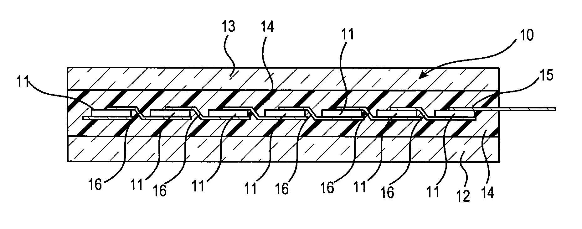
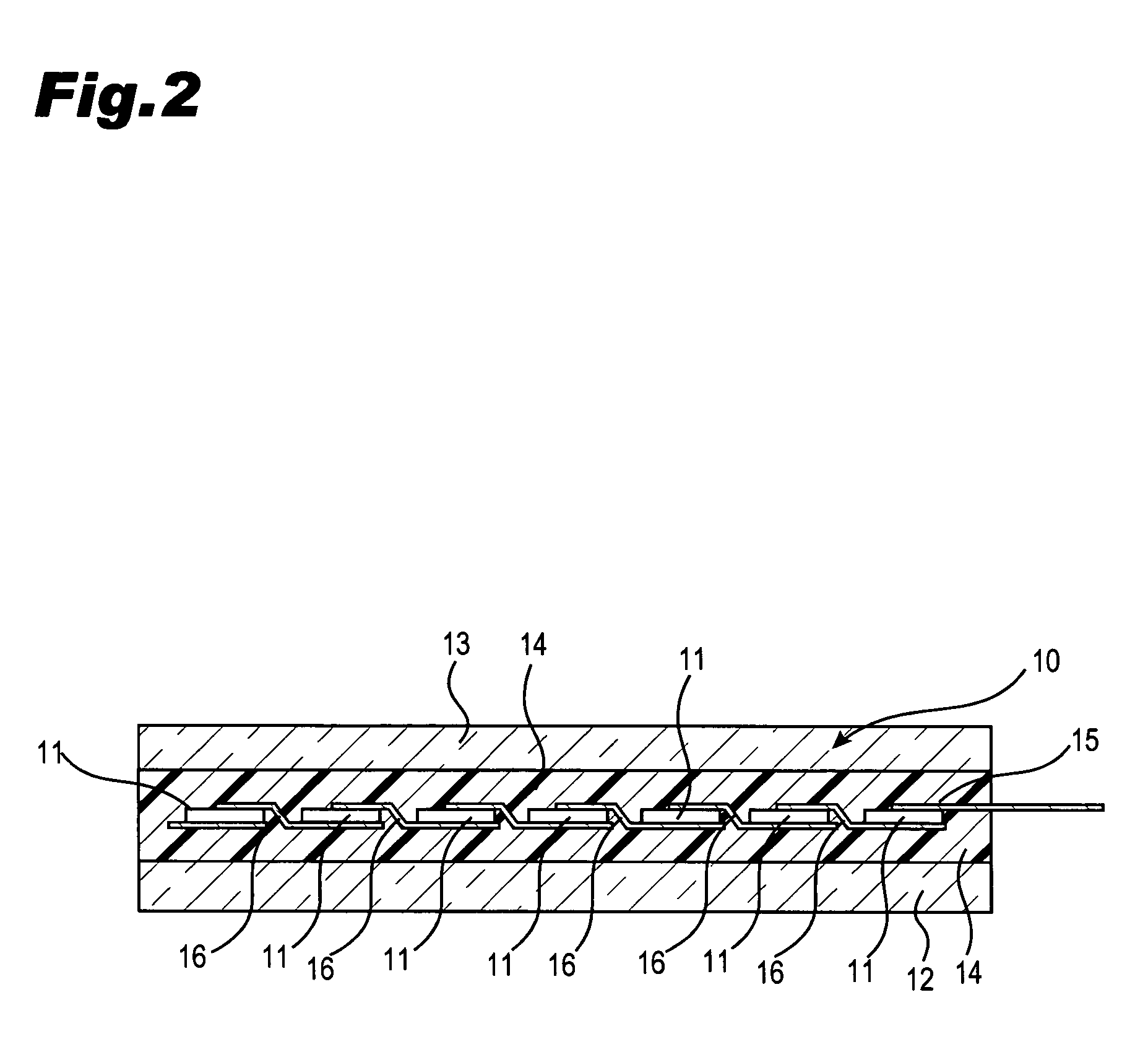
[0065]In the first embodiment, the light-receiving side light-transmitting insulative substrate 12 and the rear surface side light-transmitting insulative substrate 13 have the same dimensions. Each of the substrates 12 and 13 is made of low iron tempered glass with an outer dimension of 980 mm×1500 mm for example.

[0066]Various types of solar cells are available for the solar cell 11 such as crystalline-type, amorphous-type and the like. Recently, a solar cell which reduces loss of power generation at defective areas on its surface to realize high power generation has been in the spotlight. A substantially i-type amorphous silicon layer without dopant is interposed between a crystalline substrate and a p-type amorphous silicon layer, and between a crystalline substrate and an n-type amorphous silicon layer so as to improve interface characteristics. These solar cells 11 are connected in series or parallel to generate a specified output such as 200 W from the photovoltaic submodule 1...

third embodiment

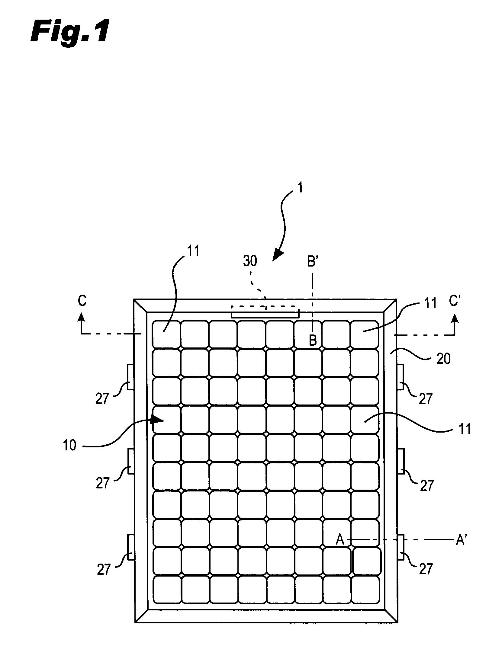
[0101]As illustrated in FIG. 16, the terminal box 30 is attached near to the edge of the rear surface side light-transmitting insulative substrate 13 of the photovoltaic submodule 10. Part of the terminal box 30 is housed in the hollow of the main body 21 through the opening 28 provided to the outer frame 20. The photovoltaic submodule 10 is set in the fitting part 22 with the upright part 38 of the terminal box 30 abutting on the inner wall of the fitting part 22. In the third embodiment, the upright part 38 is formed in such a height as to reach to the inner wall which contacts with the front surface of glass 12 of the fitting part 22. The upright part 38 is located between the inner wall of the fitting part 22 and the photovoltaic submodule 10, so that the edge of the photovoltaic submodule 10 does not contact the outer frame 20 made of metal. The photovoltaic submodule 10 is set in the fitting part 22 in such a manner that a space A through which the connecting lead 15 is guided...

fourth embodiment

[0105]Part of the terminal box 30 is housed in the hollow of the main body 21 through the opening 28 provided to the outer frame 20. The photovoltaic submodule 10 is set in the fitting part 22 with the upright part 38 of the terminal box 30 abutting on the inner wall of the fitting part 22. In the fourth embodiment, the upright part 38 is formed in such a height as to reach to the inner wall at the light receiving side of the fitting part 22. The upright part 38 is located between the inner wall of the fitting part 22 and the photovoltaic submodule 10, so that the edge of the photovoltaic submodule 10 does not contact the outer frame 20 made of metal. The photovoltaic submodule 10 is set in the fitting part 22 in such a manner that a space A through which the connecting lead 15 can be guided is maintained between the upright part 38 and the edge of the photovoltaic submodule 10.

[0106]As described above, the connecting lead 15 can be guided to the inside of the terminal box 30 throug...


PUM


Abstract

A photovoltaic module which prevents enlargement of the dimensions of a photovoltaic submodule by reducing ineffective parts which do not contribute to power generation. The photovoltaic module includes a photovoltaic submodule including a plurality of solar cells interposed between two light-transmitting substrates through the intermediary of an encapsulant, and a connecting lead extending from an edge between the two light-transmitting substrates for outputting generated electric current, a terminal box 30 attached near to the edge of the photovoltaic submodule housing a connecting part between the connecting lead and a cable for outputting generated electric current to the outside, and an outer frame set around the outer circumference of the photovoltaic submodule. An opening 28 through which the connecting lead and the terminal box are inserted is provided to the outer frame at a position which receives at least the terminal box.

Description

[0001]The priority applications Numbers JP2005-178253 and 103274 upon which this patent application is based are hereby incorporated by reference.BACKGROUND OF THE INVENTION[0002]1. Field of the Invention[0003]The present invention relates to a photovoltaic module, and is particularly suitable for a photovoltaic module which receives light on both sides.[0004]2. Description of the Related Art[0005]Photovoltaic power generation which converts light energy into electric energy by utilizing the photoelectric conversion effect is widely used as a means to obtain clean energy, which contributes to the global environment. In line with the improvement of solar cells' photoelectric conversion efficiency, many photovoltaic power generation systems using photovoltaic modules are installed for residential use.[0006]In a photovoltaic module provided with a solar cell which generates electricity utilizing sunlight, conductive materials to form a positive electrode and a negative electrode are di...

Claims


Application Information

Patent Timeline
Patent Type & Authority Patents(United States)
IPC IPC(8): H02N6/00
CPCH02S40/34H02S20/00Y02E10/50H02S30/10G03B15/07G03B15/03G03B2215/0517H04N23/56
Inventor HIKOSAKA, MASARUODA, HIROYUKIOKAMOTO, SHINGO
Owner SANYO ELECTRIC CO LTD
Why Eureka
Try Eureka