
Communication device, communication system, and communication fault detection method

a communication system and communication technology, applied in the field of communication devices, can solve the problems of considerable long port and long time-consuming maintenance of fault status, and achieve the effect of shortening the time-consuming unidirectional link fault detection

Inactive Publication Date: 2011-11-22
ALAXALA NETWORKS
View PDF4 Cites 2 Cited by
  • Summary
  • Abstract
  • Description
  • Claims
  • Application Information

AI Technical Summary

Benefits of technology

The present invention provides a communication device that can quickly detect faults in the communication links between two devices. The device includes a frame transfer unit, a link confirmation frame sending unit, and a return link confirmation frame monitoring unit. The device can confirm the status of the communication links by sending and receiving link confirmation frames. This eliminates the need for complex software processing and allows for quicker detection of faults. The device can also block frame transmission via a faulty link. The invention is useful in communication systems and communication fault detection methods.

Problems solved by technology

However, with the unidirectional link fault detection using the aforementioned UDLD, typically, the fault detection time is long, and the time required from occurrence of a fault for closing the fault occurring port is considerably long, so there is the problem that the fault status is maintained for a long time.

Method used


Image

  • Communication device, communication system, and communication fault detection method
  • Communication device, communication system, and communication fault detection method
  • Communication device, communication system, and communication fault detection method

Examples


first embodiment

A. First Embodiment

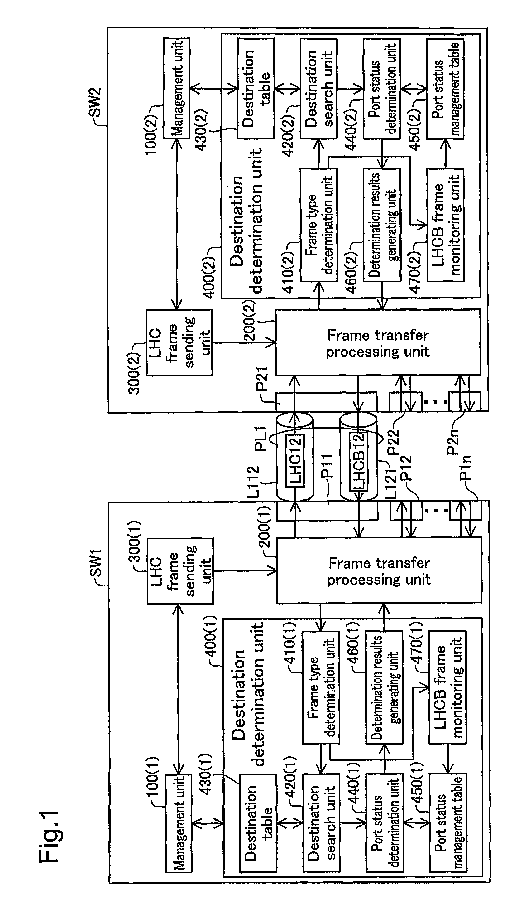
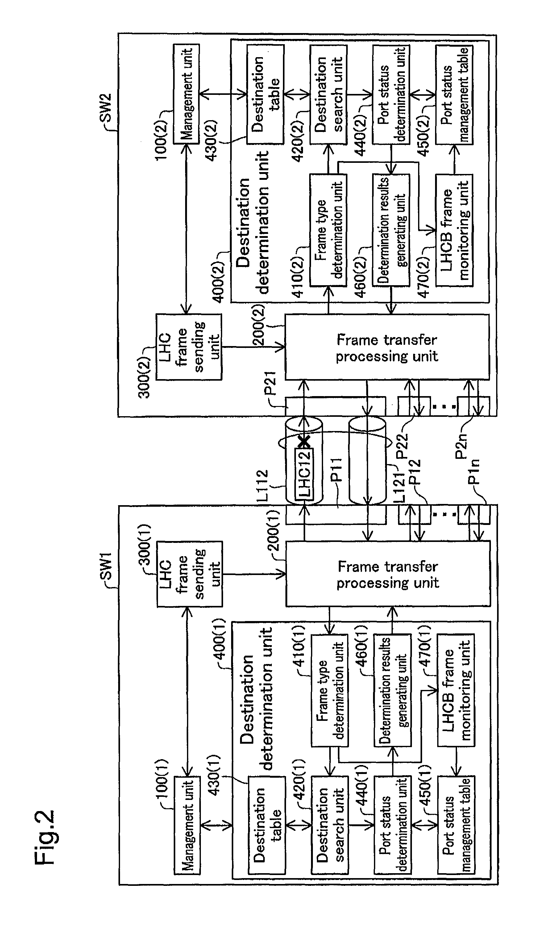
[0053]FIG. 1 and FIG. 2 are block diagrams for describing the unidirectional link fault detection executed with the communication device as the first embodiment. FIG. 1 shows a case of a normal state when a fault has not occurred, and FIG. 2 shows a case of a fault occurrence state.

[0054]A switch SW1, which is the first communication device, has a plurality of ports P11 to P1n where n is an integer of 2 or greater. The first port P11 of the first switch SW1 is connected via the physical line PL1 to the first port P21 of the plurality of ports P21 to P2n provided in a switch SW2, which is the second communication device. The physical line PL1 is constituted by two links (bidirectional link), including a first link L112 on which are sent Ethernet® frames (hereafter simply called “frames”) from the first switch SW1 toward the second switch SW2, and a second link L121 on which frames are sent from the second switch SW2 to the first switch SW1. Note that to make the de...

second embodiment

B. Second Embodiment

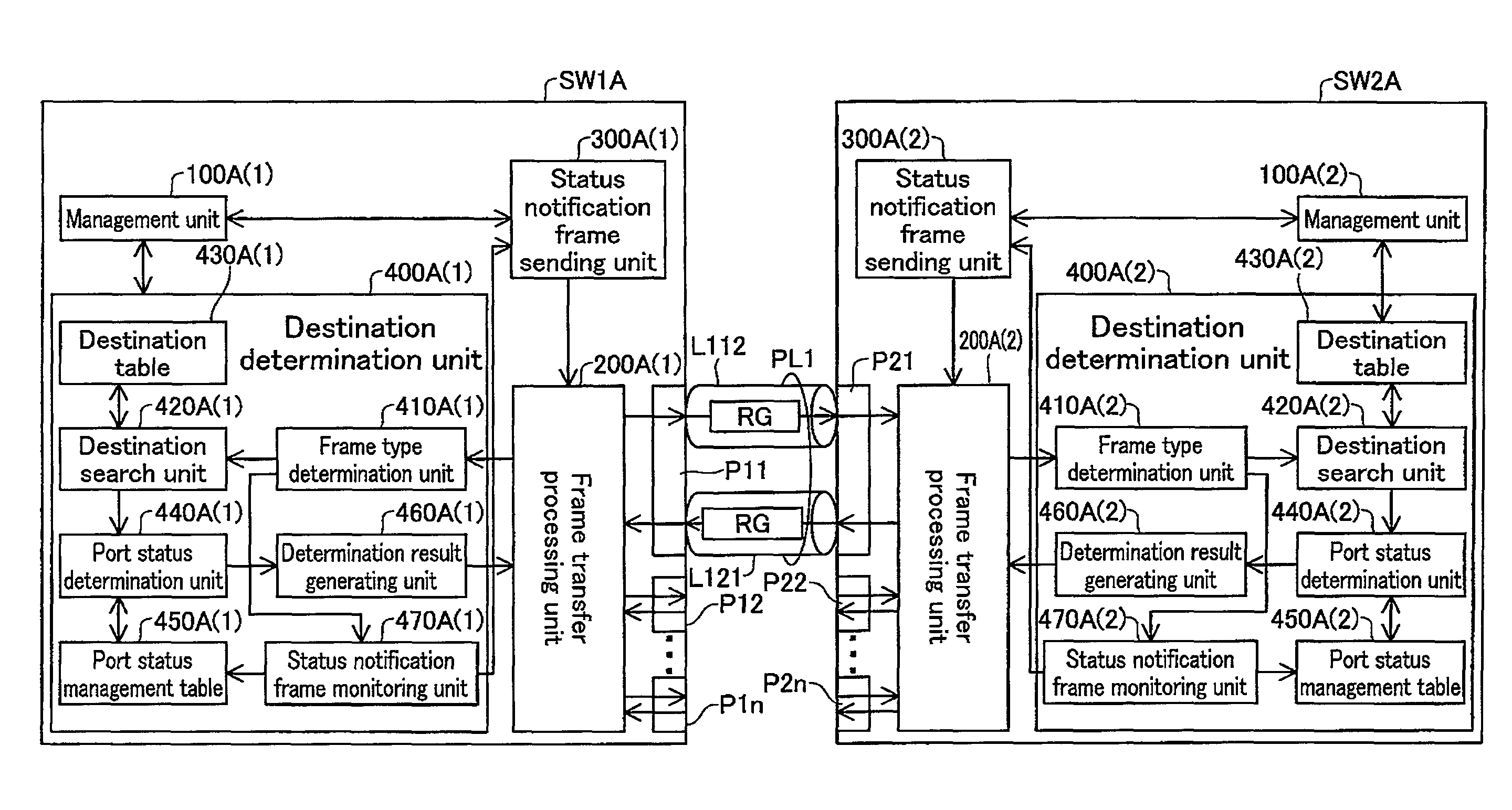
[0112]FIG. 16 and FIG. 17 are block diagrams for explaining the unidirectional link fault detection executed with the communication device as the second embodiment, where FIG. 16 shows a case of a normal status when a fault has not occurred, and FIG. 17 shows a case of a fault occurrence state.

[0113]A switch SW1A, which is the first communication device, has a plurality of ports P11 to P1n where n is an integer of 2 or greater. The first switch SW1A is connected via the physical line PL1 connected to the first port P11 to the first port P21 of the plurality of ports P21 to P2n provided in a switch SW2A which is the second communication device. The physical line PL1 is constituted by two links (bidirectional link), including a first link L112 on which are sent Ethernet frames from the first switch SW1A toward the second switch SW2A, and a second link L121 on which frames are sent from the second switch SW2A to the first switch SW1A. Note that with the second embod...


PUM


Abstract

The communication device has a frame transfer unit that executes frame transfer via the first communication link and the second communication link, a link confirmation frame sending unit, and a return link confirmation frame monitoring unit. The link confirmation frame sending unit causes the frame transfer processing unit to send a link confirmation frame for use in confirming a normal link status via the first communication link from the communication device to the counterpart communication device. The return link confirmation frame monitoring unit performs fault detection of the first and second communication links by monitoring a return link confirmation frame which is to be returned from the counterpart communication device to the communication device via the second communication link when the counterpart communication device receives the link confirmation frame via the first communication link.

Description

CROSS-REFERENCE TO RELATED APPLICATIONS[0001]The present application claims the priority based on Japanese Patent Application No. 2007-308224 filed on Nov. 29, 2007, the disclosure of which is hereby incorporated by reference in its entirety.BACKGROUND OF THE INVENTION[0002]1. Field of the Invention[0003]The present invention relates to a communication device, and particularly to a communication device for performing fault detection on a network.[0004]2. Description of the Related Art[0005]The physical line of one port connecting two communication devices is constituted by two lines, which serve a bidirectional link between the two communication devices. There are cases when a fault occurs with one link of the two links (called “unidirectional link fault”). With the unidirectional link fault, one of the communication devices is possible to send messages but not to receive, while the other of the communication devices is possible to receive messages but not to send, whereby various t...

Claims


Application Information

Patent Timeline
Patent Type & Authority Patents(United States)
IPC IPC(8): G01R31/08
CPCH04L1/24H04L1/22
Inventor AKAHANE, SHINICHIKAGANOI, TERUOKOHNO, TOMOHIKOSUGAI, KAZUO
Owner ALAXALA NETWORKS
Learn More