Power distribution monitoring system and method

a monitoring system and power distribution technology, applied in the direction of testing/monitoring control systems, program control, instruments, etc., can solve the problems of manual dispatch of field crews, difficult to quickly identify the cause and location of electrical distribution problems, and difficulty in automatic monitoring or monitoring. , to achieve the effect of minimizing the total cost of ownership and making ready costs, and low cos

Active Publication Date: 2011-11-22
ACLARA TECH LLC
View PDF38 Cites 267 Cited by
  • Summary
  • Abstract
  • Description
  • Claims
  • Application Information

AI Technical Summary

Benefits of technology

[0012]Disclosed is a remote monitoring system designed to serve the unmet need within electric utilities for low cost, system-wide, continuous monitoring of distribution circuits from 4,000 to 69,000 volts. This system makes use of radio frequency (RF) communications for bi-directional communications to a centralized system via a dynamic wireless mesh network that handles many-to-many connections. The system is also capable of dynamically updating and optimizing these connections. Additionally, the design of the system minimizes total cost of ownership and make-ready costs on the part of the electric utility by drawing its power inductively from the electrical distribution line, along with the ability to store energy to retain communicated outage information.
[0013]The system provides a near real time view of the status of distribution circuits enabling the electric utility to accurately locate a faulted element. This capability is at a much greater level of detail than that provided by SCADA systems and does not require visual inspection in the field, as Fault Circuit Indicator (FCI) devices do. The system provides reductions in the time to find the root cause of problems and dispatch repair crews to the correct location. Reduction of Mean Time to Repair (MTTR) has a direct impact on system and circuit reliability as tracked by the utility and reported to the Public Utility Commission.
[0014]The system is distinguished by the use a mesh protocol designed for sensor (MMP) overlay. A hybrid mesh approach allows the MMPs to communicate either over the air (RF) or over the electrical conductor using power line carrier communications (PLCC) technology. The exact means of communication is chosen dynamically and optimized, allowing for increased overall communication reliability and redundancy.
[0016]Finally, the system enables practical, cost-effective monitoring, as it requires minimal planning and engineering to install, does not consume any pole space, installs easily, is maintenance free and self identifies and connects to the mesh network upon installation.

Problems solved by technology

Very little automation or monitoring typically exists between the customer meter and an electrical substation, making it difficult to quickly identify the cause and location of an electrical distribution problem, e.g., an outage, without manual dispatch of field crews.
Additionally, planning and maintenance engineers in the electric utilities typically have limited information about the behavior of a circuit to drive the best decisions for circuit upgrade / rehabilitation tasks, and determining upgrade or replacement of equipment.
Very few electric utilities have widely deployed SCADA systems, and those that do are only provided with circuit level information (entire circuit faulted and open) and cannot discern a fault location along the many miles a circuit typically spans.
Electrical distribution circuits are prone to temporary faults such as nearby lightning strikes, wind-borne debris, small animals climbing insulators, and the like.
Currently, no automated system notification of power restoration exists throughout the distribution system.

Method used


Image

  • Power distribution monitoring system and method
  • Power distribution monitoring system and method
  • Power distribution monitoring system and method

Examples


Embodiment Construction

)

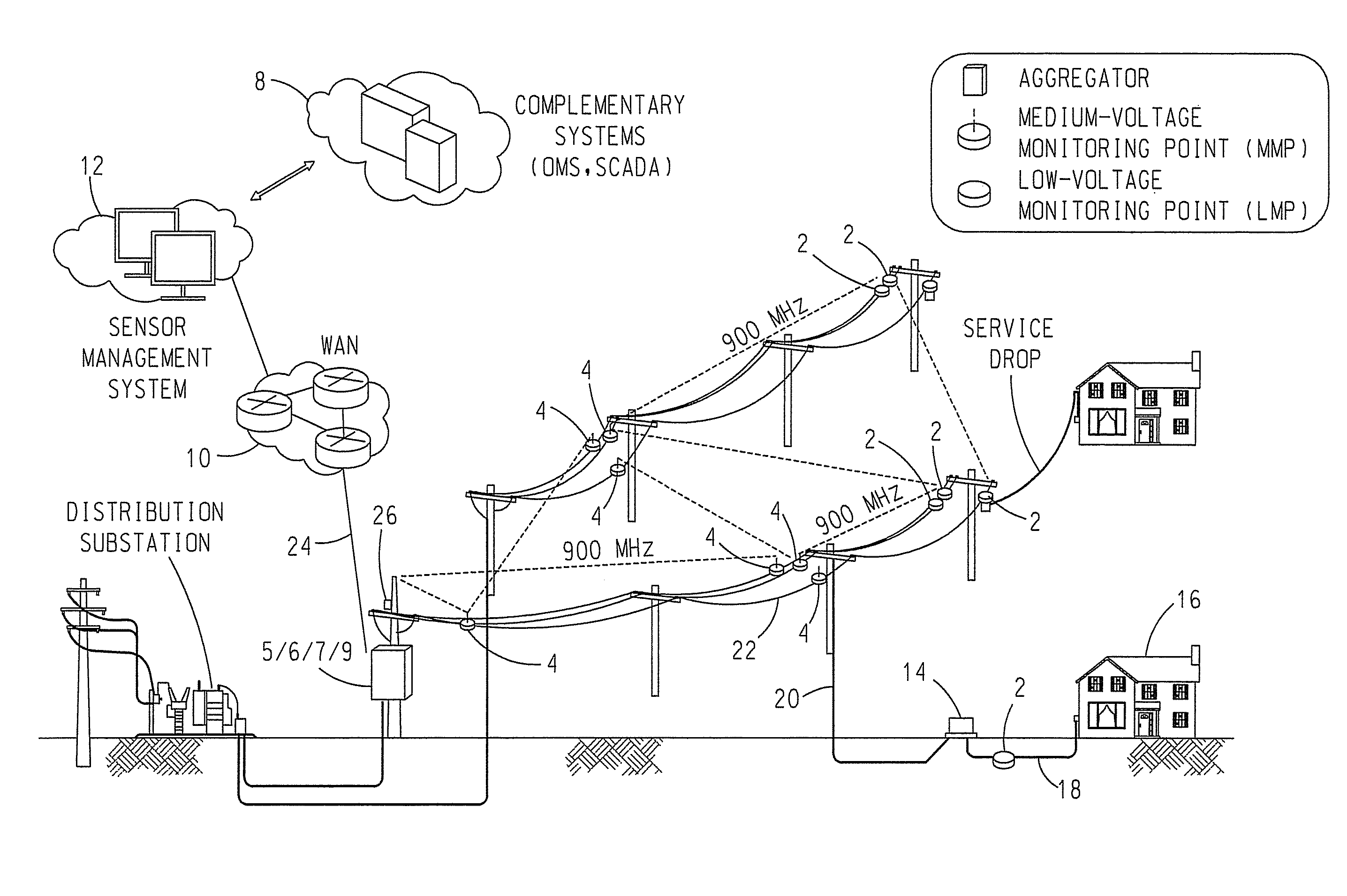
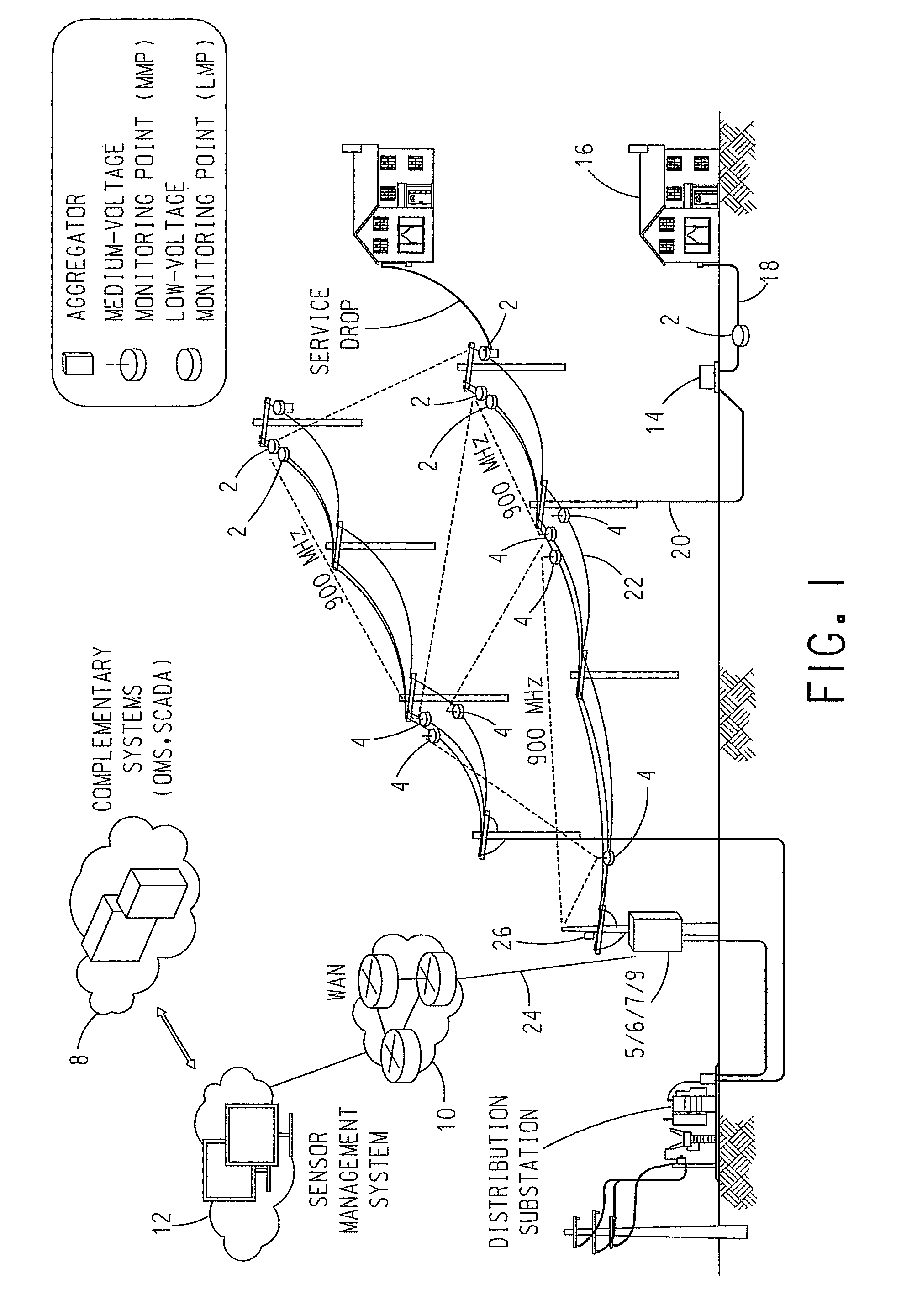
[0043]With reference to FIG. 1, a power distribution monitoring system includes distribution line sensors and supporting elements, which form an integrated wireless communication network to transport data from the field to a central location via a flexible backhaul (communication) means. The system dynamically forms its own wireless communication network, to easily build out monitoring capability across a distribution system, and can readily overcome obstacles and interferences to easily grow and expand. The system includes sensors that communicate wirelessly to an aggregation point which bridges the wireless communication network to a point of backhaul (communication) into the utility's network.

[0044]The system desirably uses a 900 MHz mesh for wireless communications among sensors. However, this is not to be construed as limiting the invention. A radio transceiver (RT) is implemented in a modular fashion in each sensor to allow future incorporation of alternate RF frequencies and...


PUM


Abstract

A power distribution monitoring system includes a number of power line mounted monitors. Each monitor can acquire data regarding the delivery of electrical power in the power line, wirelessly transmit and receive messages, and electromagnetically acquire and store operating electrical power from electrical current flowing in the power line. The system also includes an aggregator that can wirelessly transmit and receive messages and wirelessly output beacon messages. In response to beacon signals wirelessly output by the aggregator, each monitor co-acts with the aggregator to dynamically build a wireless communication network for the wireless communication of the data acquired by the monitor regarding the delivery of electrical power in the power line to the aggregator.

Description

CROSS-REFERENCE TO RELATED APPLICATION[0001]The present application claims priority from U.S. Provisional Patent Application No. 61 / 015,289, filed Dec. 20, 2007, which is incorporated herein by reference.BACKGROUND OF THE INVENTION[0002]1. Field of the Invention[0003]The present invention relates to an intelligent electrical distribution grid monitoring system and method that includes a network of sensors that communicate via auto discovery and mesh technology. Each sensor is inductively powered from the electrical conductor and adaptively communicates via a radio, via the electrical conductor, or both simultaneously.[0004]2. Description of Related Art[0005]The electric distribution grid in North America is characterized by aging infrastructure and outdated technology at a time when digital society demands an increased quantity and more reliable electrical power. As the investment cycle within the electricity distribution industry reaches a critical juncture for reinvestment in and ...

Claims


Application Information

Patent Timeline
Patent Type & Authority Patents(United States)
IPC IPC(8): G01R21/00H04B7/212H04B3/00
CPCG01R22/063
Inventor GIBALA, JEFFREY A.NERO, REGIS J.DAY, STEVEN P.CIMBALA, MATTHEW G.SMITH, ROGER A.
Owner ACLARA TECH LLC
Why Eureka
Try Eureka