
Eye tracker having an extended span of operating distances

a technology of eye tracking and operating distance, which is applied in the field of automatic eye tracking, can solve the problems of comparatively low quality requirements for the lens structure, and achieve the effects of reliable automatic eye tracking, large variations in ambient light conditions, and robust and cost-effectiveness

Active Publication Date: 2011-11-29
TOBII TECH AB
View PDF14 Cites 37 Cited by
  • Summary
  • Abstract
  • Description
  • Claims
  • Application Information

AI Technical Summary

Benefits of technology

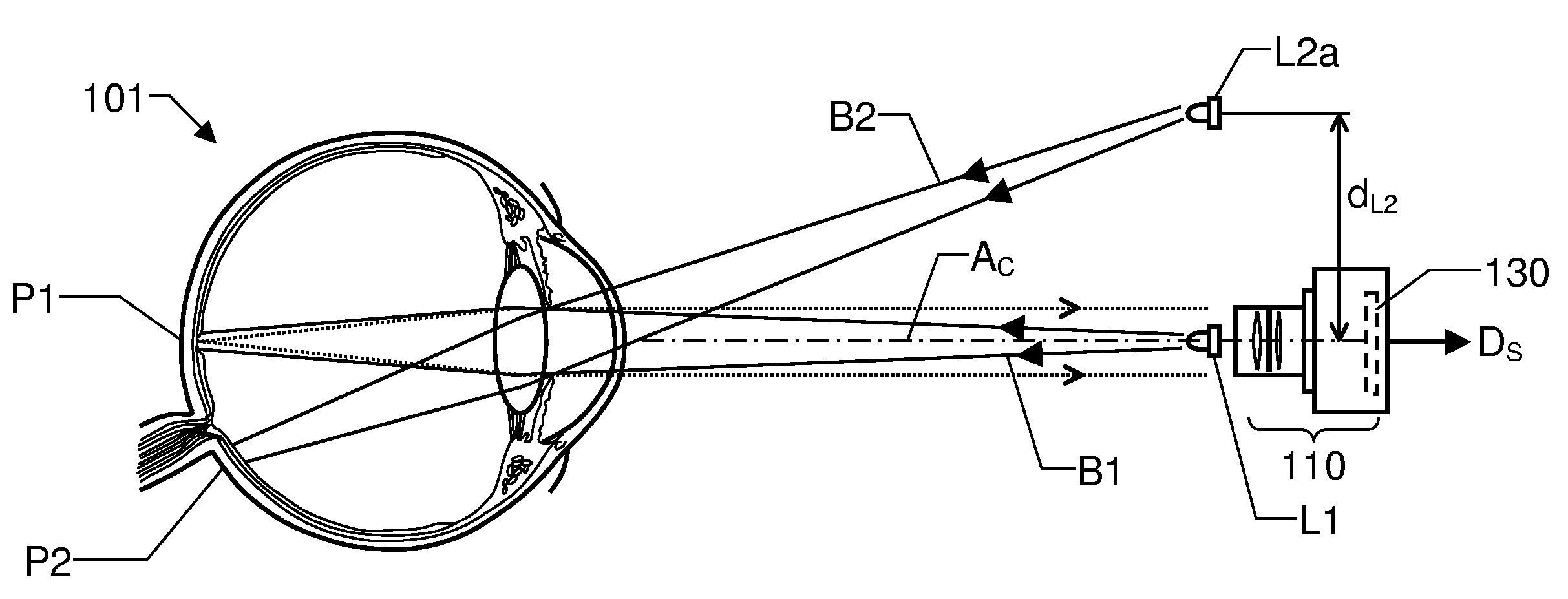
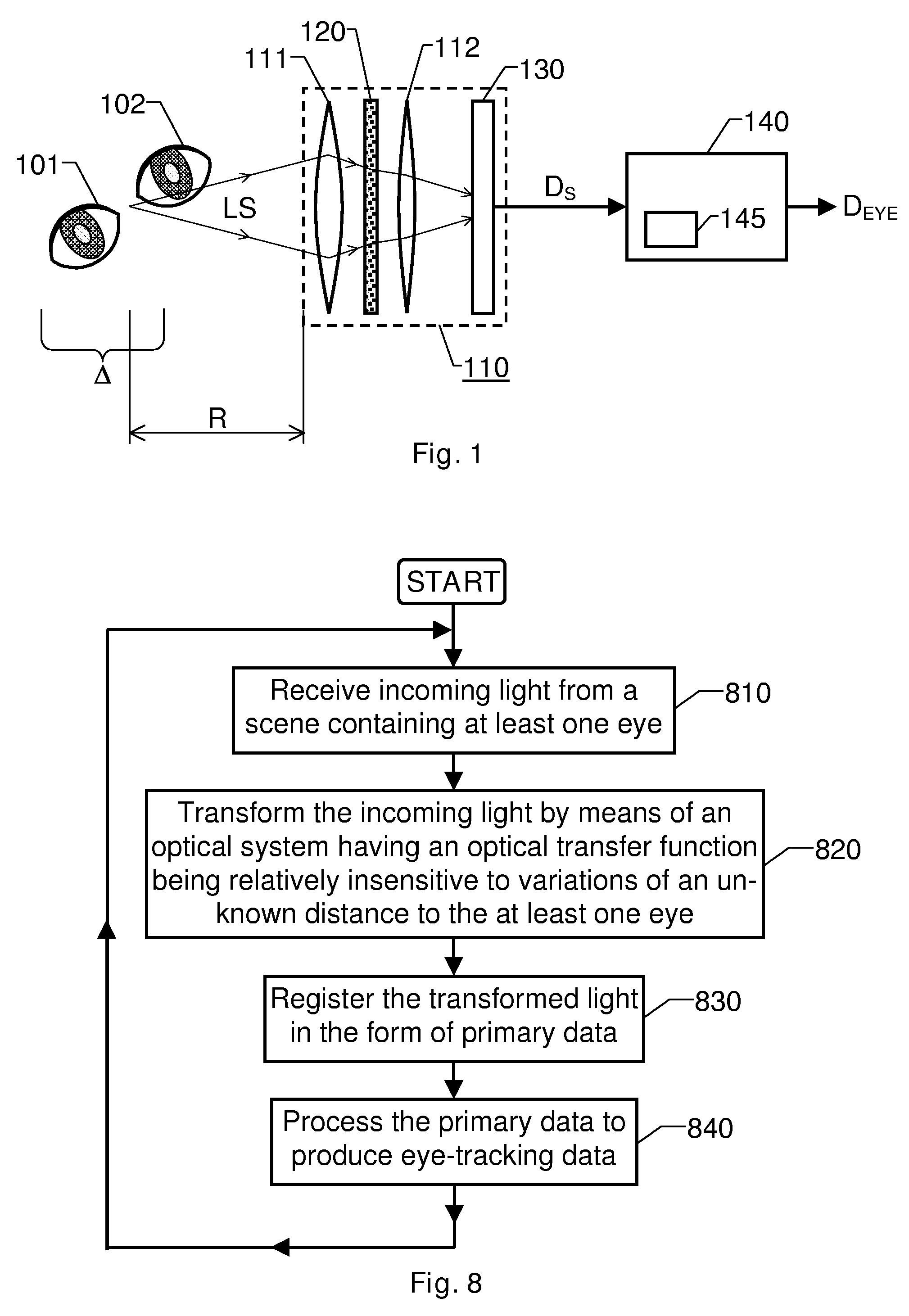
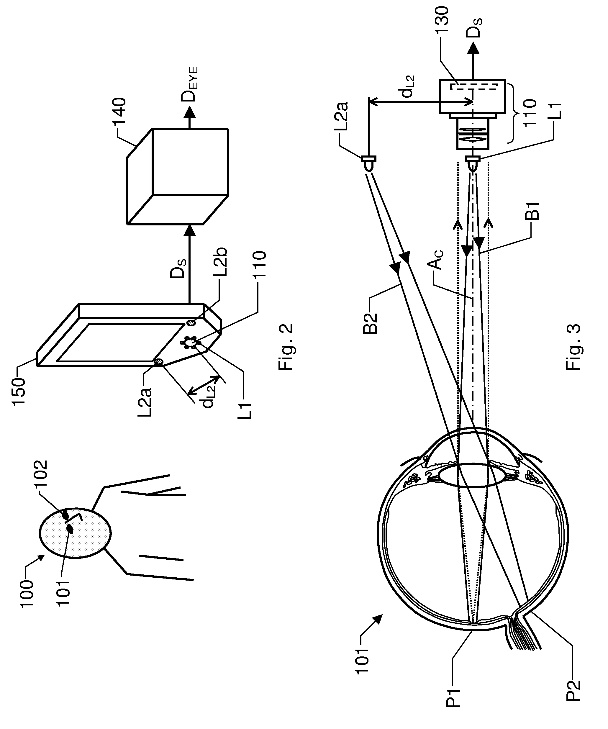
[0007]The object of the present invention is therefore to provide a robust and cost-efficient solution, which alleviates the above problems and thus enables a reliable automatic eye tracking over a relatively long range of distances to the user, and which also allows comparatively large variations in the ambient light conditions.

Problems solved by technology

Furthermore, the quality requirements on the lens structure may be comparatively low, which vouches for low cost,

Method used


Image

  • Eye tracker having an extended span of operating distances
  • Eye tracker having an extended span of operating distances
  • Eye tracker having an extended span of operating distances

Examples


first embodiment

[0056]FIG. 5 illustrates how a mask 120 according to the invention may be used to benefit from the above-mentioned bright- and dark-pupil effects accomplished by the at least one first light source L1 and the at least one second light source L2a and L2b respectively in the processing performed by the proposed processing device 140.

[0057]In this example, the mask 120 and a lens 113 are adapted to realize a first optical transfer function with respect to light within the first wavelength range λAL-λAU, and realize a second optical transfer function with respect to light within the second wavelength range λBL-λBU. As a result, light within the first wavelength range λAL-λAU is directed towards a first area Al on a sensor surface of the image sensor 130, and direct light within the second wavelength range λBL-λBU is directed towards a second area A2 on the sensor surface.

[0058]For reasons of a clear presentation the first and second optical transfer functions are here symbolized by two ...

second embodiment

[0061]FIG. 6 illustrates how a sensor area of an image sensor 130 is configured according to the invention. Also in this embodiment, the design is intended to enable the processing performed by the processing device 140 to benefit from the bright- and dark-pupil effects accomplished by the at least one first light source L1 and the at least one second light source L2a and L2b respectively.

[0062]Here, however, the sensor 130 has two types of sensor elements, namely a first set of elements 130a wherein each element (symbolized by means of a white square) is adapted to detect light within the first wavelength range λAL-λAU, and a second set of sensor elements 130b wherein each element (symbolized by means of a dark square) is adapted to detect light within the second wavelength range λBL-λBU. Thus, the first set of sensor elements 130a register a first sub-set of the primary data Ds representing bright-pupil information, and the second set of sensor elements 130b register a second sub-...


PUM


Abstract

The present invention relates to automatic registration and tracking of the eyes of at least one subject. An optical system, including a lens structure, a mask and an image sensor, receives incoming light from a scene containing the subject and directs at least a portion of this light towards the image sensor, which registers spatially distributed light and thus produces primary data. The mask is to alter a basic optical transfer function of the lens structure and the image sensor into an enhanced optical transfer function, which is substantially less sensitive to variations of an unknown distance between the optical system and the subject than the basic optical transfer function. The processing unit is to receive the primary data and process this data to produce resulting eye-tracking data representing a position estimate of the at least one eye and / or a gaze direction for the at least one eye.

Description

CROSS REFERENCE TO RELATED APPLICATIONS[0001]The present application claims priority to U.S. Provisional Patent Application Ser. No. 60 / 726,065 titled “Eye Tracker Having an Extended Span of Operating Distances” filed on Oct. 12, 2005.THE BACKGROUND OF THE INVENTION AND PRIOR ART[0002]The present invention relates generally to automatic eye tracking wherein the tracking precision is enhanced based on an optical-transfer-function modifying mask, which enables the eye tracker to work within a relatively large range of distances. More particularly the invention relates to a system according to the preamble of claim 1 and a method according to claim 14. The invention also relates to a computer program according to claim 23 and a computer readable medium according to claim 24.[0003]The concept of eye tracking is well known in the art, and a number of different techniques have been developed for accomplishing automatic eye and gaze tracking. In the area of remote, non-obtrusive eye tracki...

Claims


Application Information

Patent Timeline
Patent Type & Authority Patents(United States)
IPC IPC(8): A61B3/14G06V10/143
CPCA61B3/113G06K9/2018G06T7/20G06K9/00604G06V40/19G06V10/143
Inventor SKOGO, MARTENELVESJO, JOHNREHNSTROM, BENGT
Owner TOBII TECH AB
Learn More