
Luminaire quick mount universal bracket system and method

a universal bracket and light fixture technology, applied in the field of universal bracket systems, can solve the problems of time-consuming and cumbersome process, fixtures that have a tendency to rattle, and dangerous process, and achieve the effect of quick mounting, preventing fixture rattling, and preventing the risk of the housing being dropped

Inactive Publication Date: 2011-11-29
EATON INTELLIGENT POWER LIMITED
View PDF21 Cites 9 Cited by
  • Summary
  • Abstract
  • Description
  • Claims
  • Application Information

AI Technical Summary

Benefits of technology

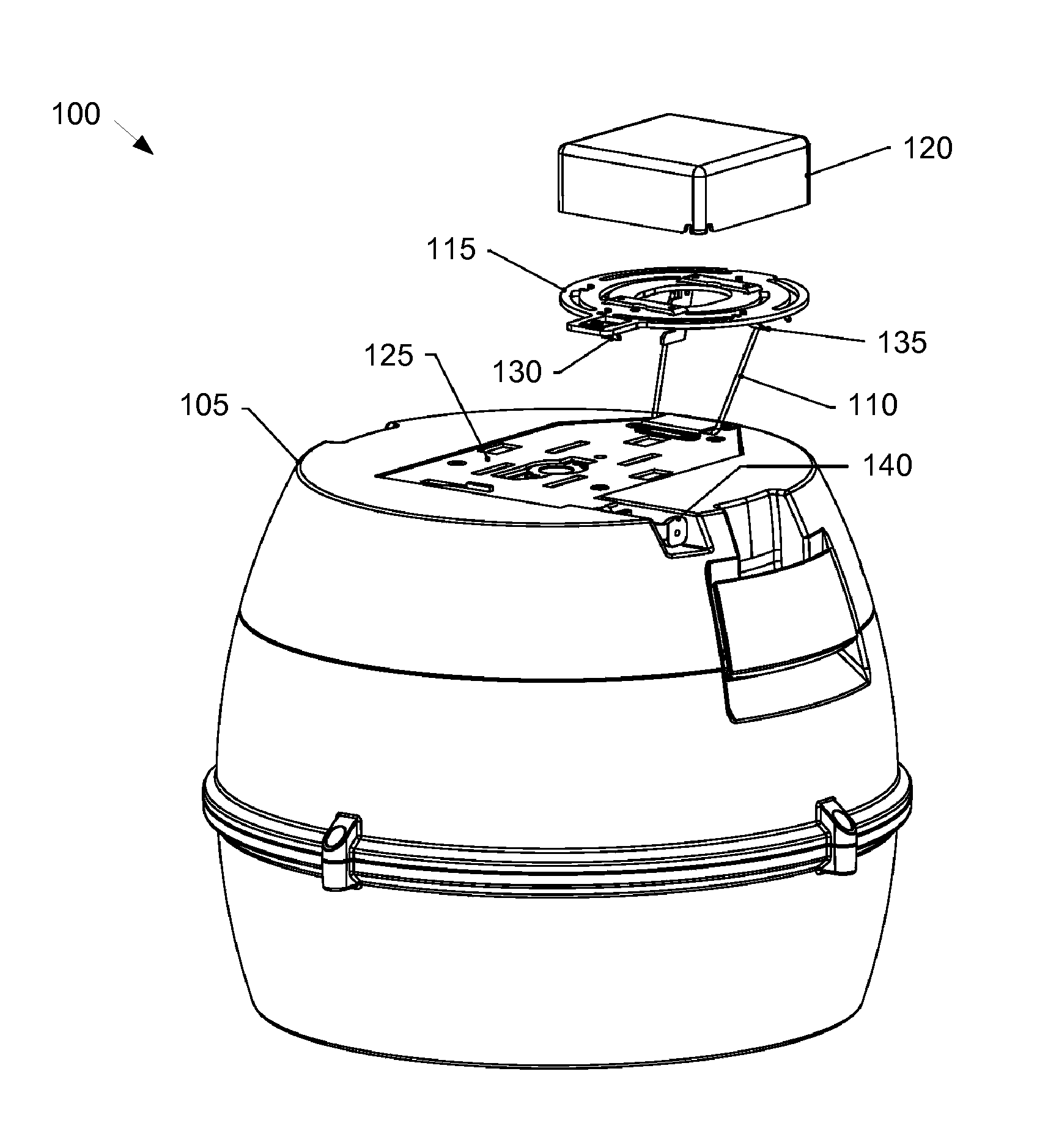
[0006]The luminaire quick-mount universal bracket system allows for quickly mounting, securing, and accessing components of a light fixture without the use of tools, while also helping to prevent rattling of the fixture. The luminaire system can include a housing, a universal bracket, and a hanging hook. The hanging hook can attach to the housing and the universal bracket, so that the housing swivels away from the universal bracket without the risk of the housing being dropped. The universal bracket can be connected to a junction box or other desirable location. The universal bracket can include a locking spring for securing the housing in place and a reinforced spring for applying tension to the housing to help prevent rattling. The housing can include a button or other release mechanism that allows the housing to be released from the universal bracket without the need for a tool.

Problems solved by technology

This process, however, is time consuming and cumbersome.
In addition, this process is dangerous because the person could accidentally drop the housing from the overhead location while disconnecting it and / or accessing the electrical components.
Further, because conventional light fixtures are attached to the housing through the use of screws and / or bolts, the fixtures have a tendency to rattle during periods of vibration.
This rattling may cause unnecessary noise and ultimate failure of the components of the light fixture.

Method used


Image

  • Luminaire quick mount universal bracket system and method
  • Luminaire quick mount universal bracket system and method
  • Luminaire quick mount universal bracket system and method

Examples


Embodiment Construction

[0017]A quick-mount universal bracket system includes a housing and a universal bracket. The housing and universal bracket are connected to one another by a hanging hook, which allows the housing to rotate away from the universal bracket while still being safely attached thereto. The inventive functionality of the quick-mount universal bracket system will be explained in more detail in the following description an is disclosed in conjunction with the presented figures.

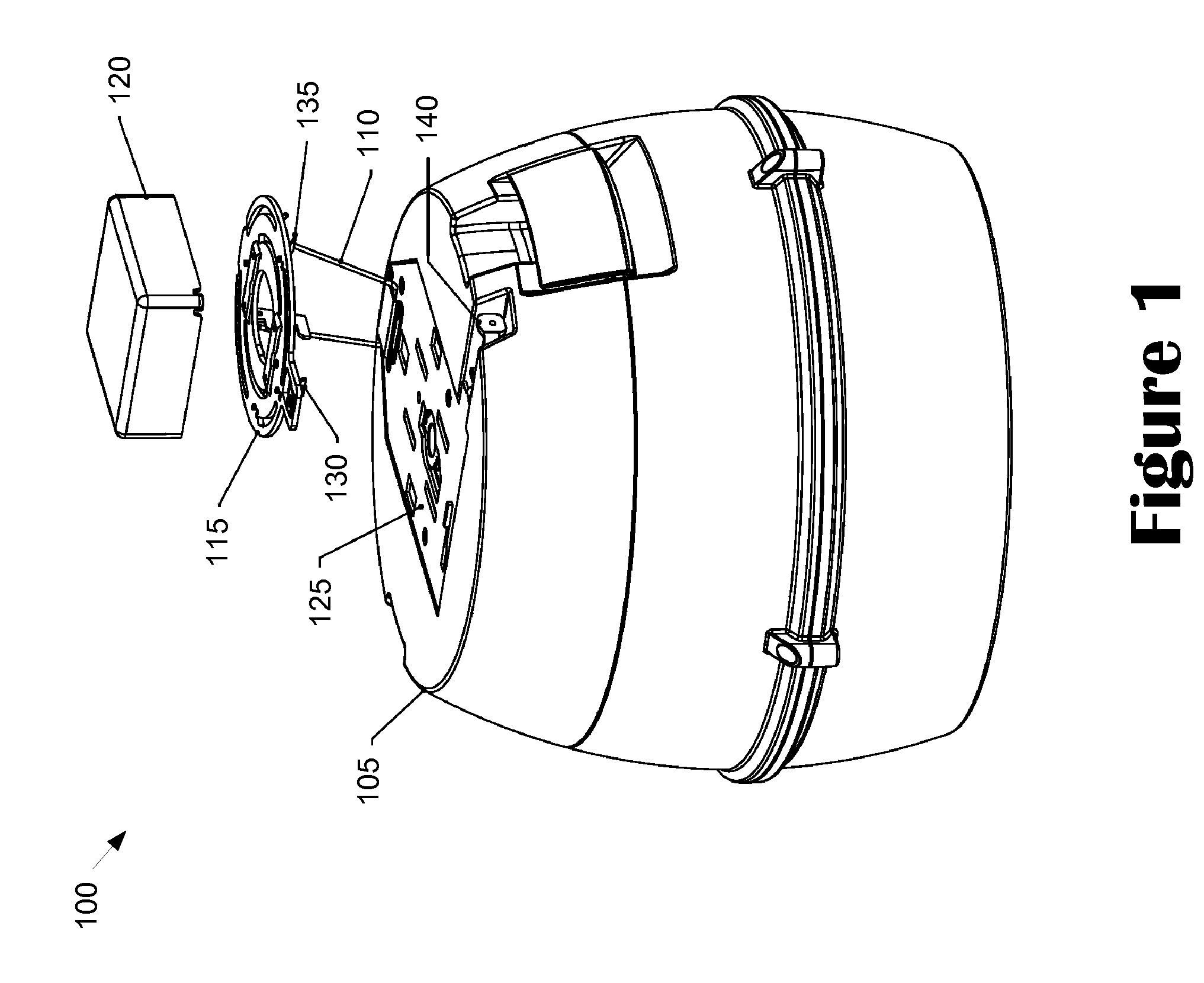
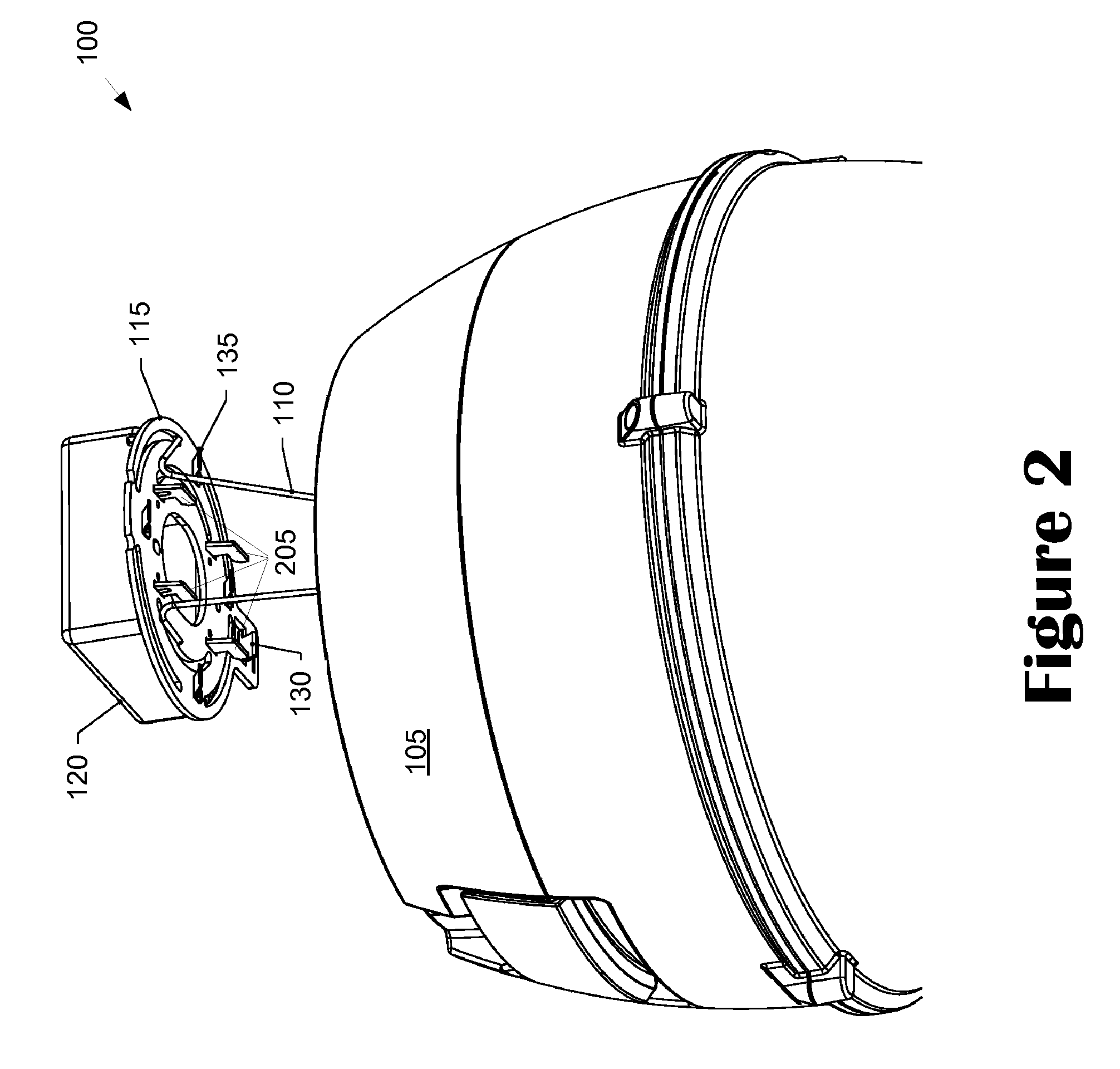
[0018]Turning now to the drawings, in which like numerals indicate like elements throughout the several figures, exemplary embodiments of the invention are described in detail. FIG. 1 is a perspective view of a luminaire system using a quick-mount universal bracket 100, according to an exemplary embodiment of the invention. FIG. 2 is a partial perspective view of the luminaire system using the quick-mount universal bracket 100, according to an exemplary embodiment of the invention. FIG. 3 is an elevation view of the qu...


PUM


Abstract

A luminaire system provides for mounting and accessing a light fixture housing without tools. A universal bracket is coupled to the junction box along the ceiling and engages with a top mounting plate affixed to the housing. One or more slide hooks appended to the universal bracket allows the top mounting plate to mount to the universal bracket, and a reinforced spring and locking spring keeps the light fixture housing in place, while preventing rattling between the universal bracket and the top-mounting plate. The housing can be removed from the electrical junction box through the use of a release button affixed to the housing. The button disengages the locking spring from the top mounting plate, thereby allowing the housing to swivel away from the universal bracket and junction box by way of a hanging hook. The hanging hook supports the housing when released from the universal bracket.

Description

TECHNICAL FIELD[0001]The invention relates generally to light fixtures and more particularly to a universal bracket system for mounting, securing, and accessing components of a light fixture.BACKGROUND[0002]A luminaire is a system for producing, controlling, and / or distributing light for illumination. For example, a luminaire can include a system that outputs or distributes light into an environment, thereby allowing certain items in that environment to be visible. Luminaires are sometimes referred to as “light fixtures.”[0003]A luminaire may be attached or suspended from an overhead location, such as a ceiling. A typical luminaire includes electrical components contained within a housing, a lamp socket coupled to the electrical components and a reflector or diffuser mounted to the lamp housing. For suspended luminaries, one or more cables connecting the housing to an overhead location can also be included. The lamp socket is configured to receive a light-emitting element, such as a...

Claims


Application Information

Patent Timeline
Patent Type & Authority Patents(United States)
IPC IPC(8): F21V15/01
CPCF21V21/00F21V21/02F21V21/30
Inventor VANN, STEENWEI, SUN YUAN
Owner EATON INTELLIGENT POWER LIMITED
Learn More