

Modular hip joint implant
a hip joint and module technology, applied in the field of modular hip joint implants, can solve the problems of still being bulky or cumbersome to obtain modular components, and achieve the effect of improving the stability and stability of the hip join
- Summary
- Abstract
- Description
- Claims
- Application Information
AI Technical Summary
Benefits of technology
Problems solved by technology
Method used
Image

Examples
Embodiment Construction
[0031]The following description of various embodiments is merely exemplary in nature and is in no way intended to limit the invention, its application, or uses. For example, although the invention is illustrated for a hip implant, the invention can be used with any type of prosthesis for a bone such as, for example, a proximal or distal femur, a proximal or distal tibia, a pro
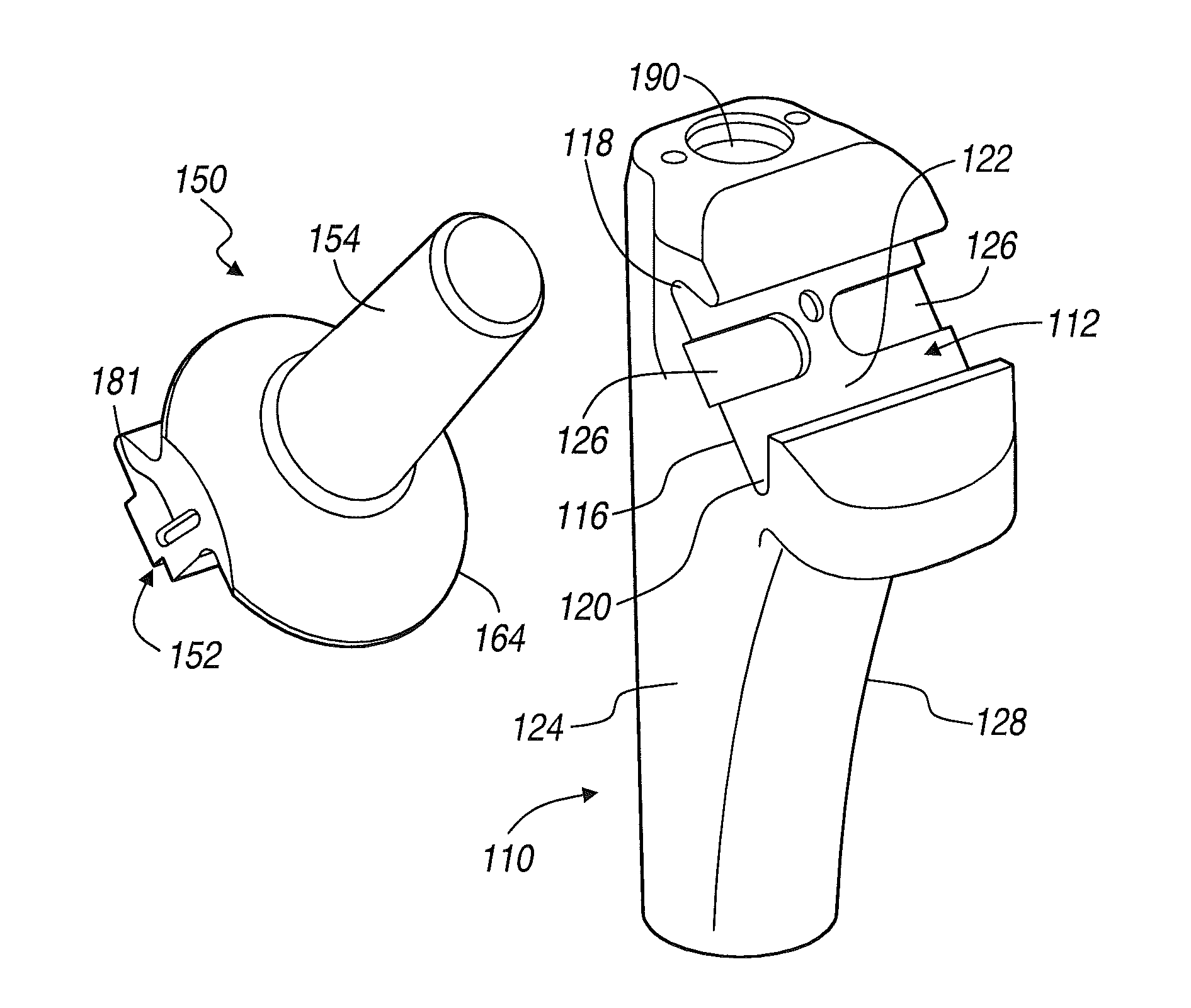
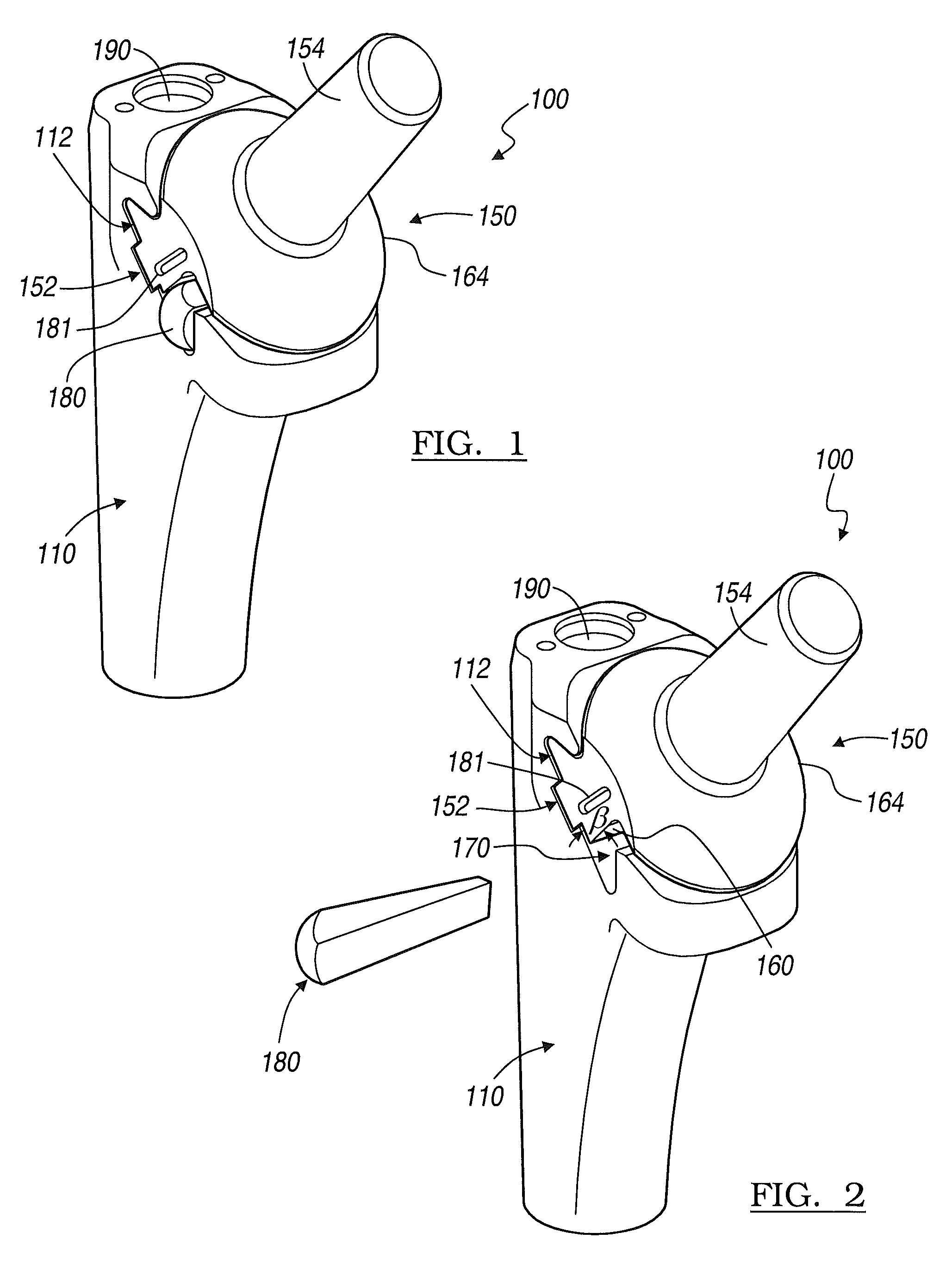
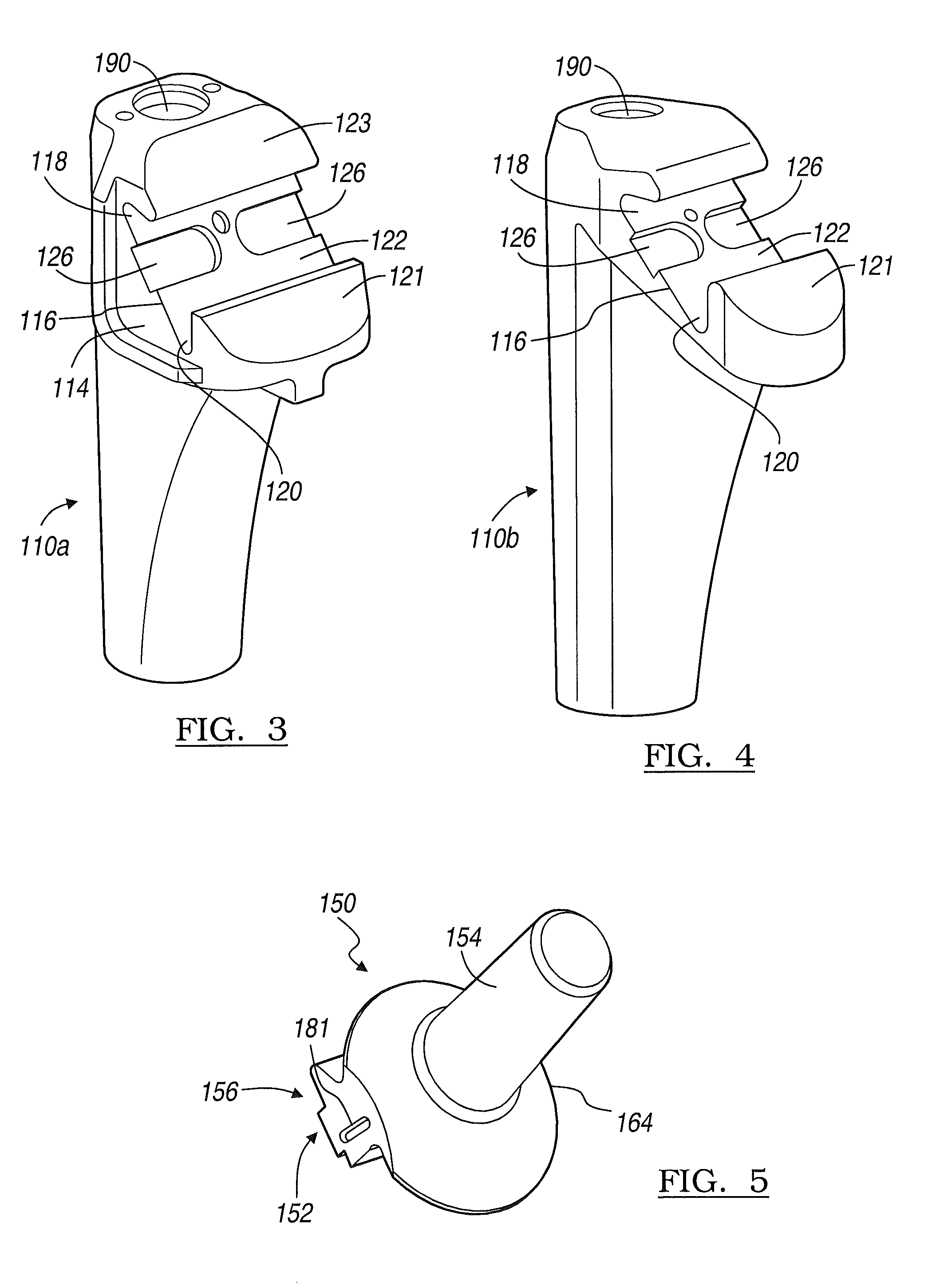
[0032]FIGS. 1, 13 and 14 illustrate respectively an exemplary of a modular hip joint implant 100 and an exemplary modular hip replacement system 300. The implant 100 includes a femoral stem 110, a neck component 150, and a key 180. The femoral stem 110 and the neck component 150 have opposing interlocking proximal stem and distal neck surfaces 112, 152, which allow for relative sliding therebetween, as best seen in FIGS. 8 and 9. When interlocked, the femoral stem 110 and neck component 150 define a keyway 170. The key 180 can be wedged into the keyway 170 to lock the components of the modular hip joint implant...
PUM
 Abstract
Description
Claims
Application Information