Power tool

a power tool and tool body technology, applied in the direction of motor/generator/converter stopper, dynamo-electric converter control, instruments, etc., can solve the problem of turning off the main conta

Active Publication Date: 2011-11-29
KOKI HLDG CO LTD
View PDF10 Cites 23 Cited by
  • Summary
  • Abstract
  • Description
  • Claims
  • Application Information

AI Technical Summary

Benefits of technology

[0009]In respect of the above, an object of the present invention is to provide a power tool which is capable of preventing a motor from being stopped regardless of whether an operator has removed his / her hands off a trigger switch.
[0028]With the above configurations, the occurrence of the malfunction of stopping of a motor against an operator's will can be prevented.

Problems solved by technology

When the start or stop of the motor is controlled in response to only an ON / OFF state of a main contact, there is a possibility that, regardless of whether an operator has moved his / her hands off the trigger switch, the main contact is turned OFF due to some reasons such as vibration, noise, or the like.

Method used


Image

  • Power tool
  • Power tool
  • Power tool

Examples


Embodiment Construction

[0035]An impact driver of an embodiment of the present invention is described with referring to attached drawings below.

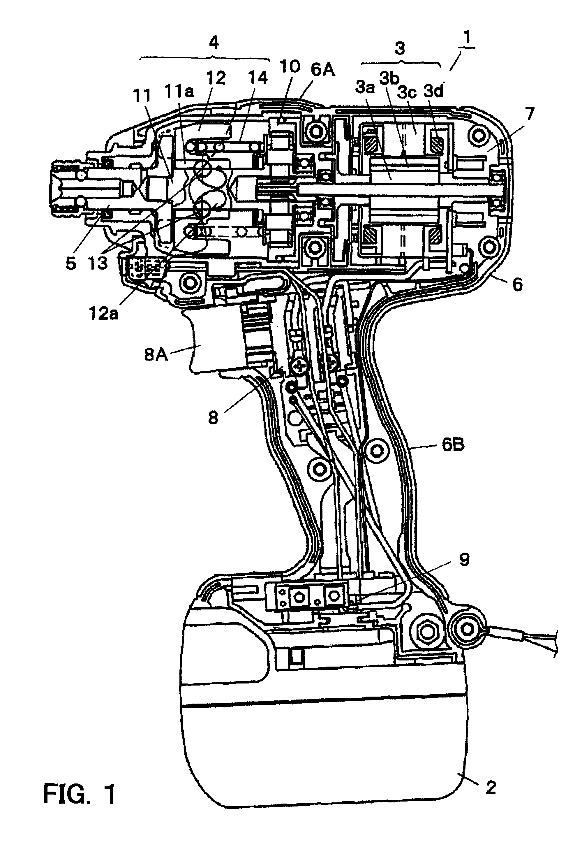
[0036]First, with referring to FIG. 1, mechanical configurations and operations of the impact driver 1 will be described.

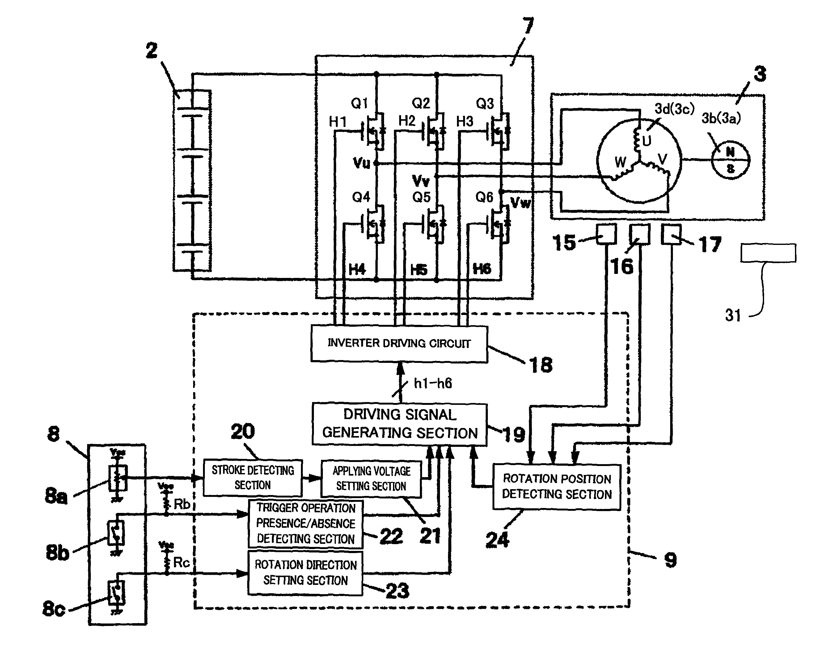
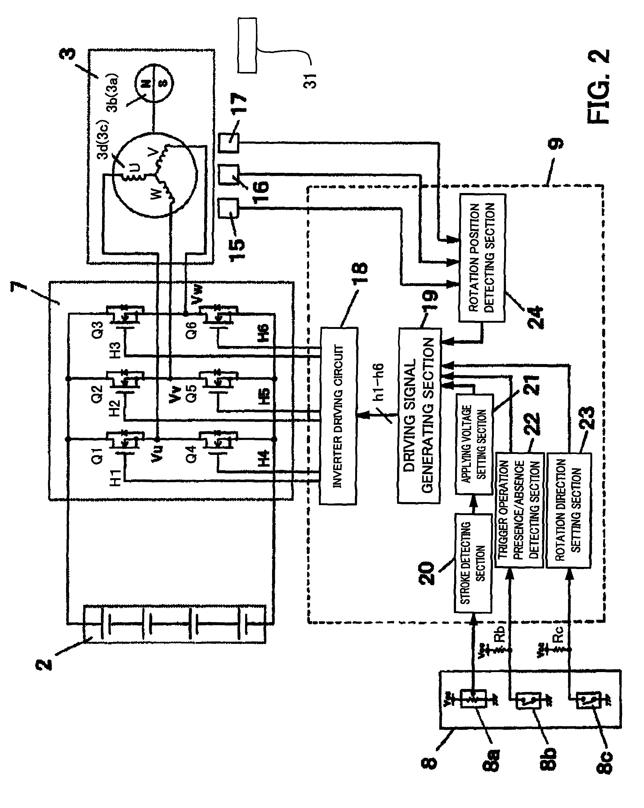
[0037]The impact driver 1 of the embodiment, as shown in FIG. 1, includes a battery 2, a motor 3, a rotation / impact mechanism 4, an anvil 5, a housing 6, an inverter section 7, a trigger switch 8, and a control section 9. The rotation / impact mechanism 4 is driven by using a chargeable battery 2 as a power source and the motor 3 as a driving source. The rotation and impact mechanism 4 provides rotational impact (rotation and impact) to the anvil 5 serving as an output shaft by driving the motor 3. The anvil 5 transfers the rotational impact provided from the rotation / impact mechanism 4 to tip tools such as a driver bit mounted on the anvil 5 to perform work such as screwing or the like.

[0038]The motor 3 is made up of a brushless DC (Direct Current...


PUM


Abstract

The controller determines the presence or absence of operation of the trigger switch according to an ON / OFF state of the main contact of the trigger switch and designating the rotation speed of the motor based on a signal outputted from the speed contact. The controller stops the rotation of the motor, after the trigger switch is activated and the main contact is turned ON and the motor is driven according to a signal outputted from the speed contact, when an OFF state of the main contact is detected, only in the case where a signal value outputted from the speed contact is a predetermined value or less.

Description

BACKGROUND OF THE INVENTION[0001]1. Field of the Invention[0002]The present invention relates to a power tool configured to control the rotation speed of a motor in accordance with an amount of operation of a trigger switch.[0003]2. Description of the Related Art[0004]There are power tools which rotate tip tools such as a drill, driver, or a like by using a motor as a driving source. Of these types of power tools, there is a power tool which controls the rotation speed of a motor in accordance with an amount (degree) of operation of a trigger switch. In general, such power tool is configured to control the rotation speed of a motor by varying a voltage applied to the motor in accordance with an amount (degree) of operation (stroke) of the trigger switch.[0005]Generally, the power tool of this type increases (or decreases) a voltage applied to the motor in accordance with an increase (or a decrease) in the amount of operation (stroke) of the trigger switch to exert control so that th...

Claims


Application Information

Patent Timeline
Patent Type & Authority Patents(United States)
IPC IPC(8): H02P7/00B25F5/00
CPCB25F5/00
Inventor WATABE, SHINJIIWATA, KAZUTAKATAKANO, NOBUHIRO
Owner KOKI HLDG CO LTD
Why Eureka
Try Eureka