
Method and apparatus for real-time motion correction for ultrasound spatial compound imaging

a technology of ultrasound and compound imaging, applied in the field of ultrasound imaging, can solve the problems of poor image quality, preventing reliable analysis of images, and reducing signal-to-noise ratios

Active Publication Date: 2011-11-29
GENERAL ELECTRIC CO
View PDF19 Cites 13 Cited by
  • Summary
  • Abstract
  • Description
  • Claims
  • Application Information

AI Technical Summary

Benefits of technology

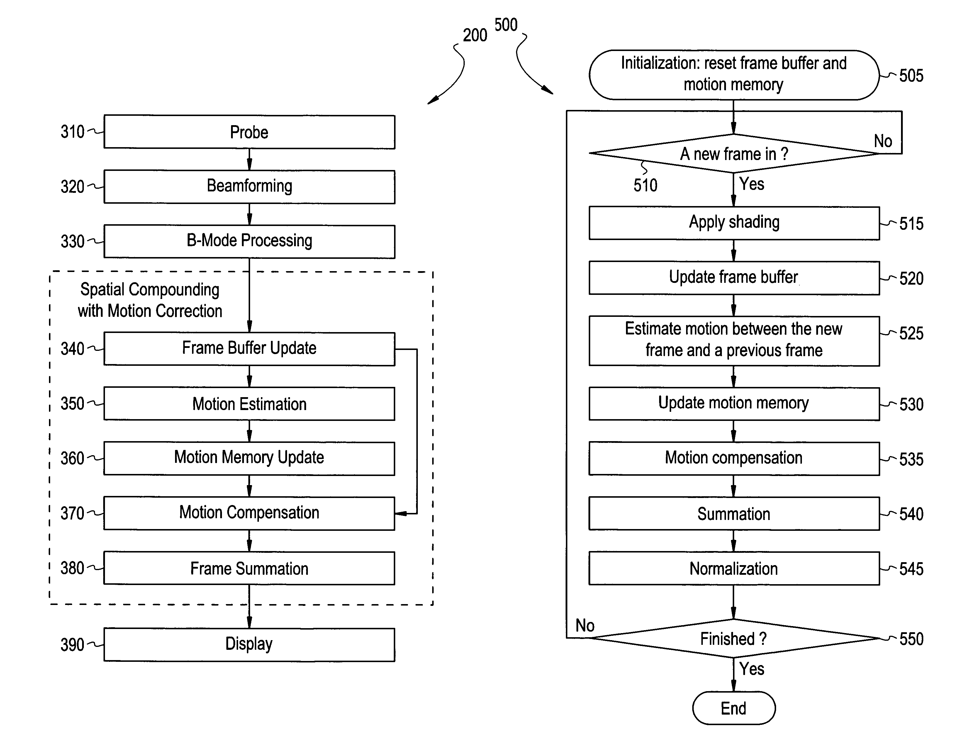
"The present invention provides a method and system for real-time motion correction in compound ultrasound imaging. This allows for improved image quality and reduced blurring in the resulting images. The method involves estimating motion between image frames, updating a previous motion estimate with the estimated motion to form an updated motion estimate, and correcting one or more previous image frames using the updated motion estimate. The method may also include forming a compound image from the image frames and updating a previous motion estimate with the motion estimate. The system includes a frame buffer, memory, and processor for estimating motion, correcting frames, and combining frames to form a spatial compound image. The technical effects of the invention include improved image quality, reduced blurring, and improved spatial compound imaging."

Problems solved by technology

Therefore, a signal-to-noise ratio decreases since noise generated by the ultrasound system's signal amplifiers, for example, may not be reduced to arbitrary low levels.
Poor image quality may prevent reliable analysis of the image.
For example, a decrease in image contrast quality may yield an unreliable image that is not usable clinically.
However, a spatial compounded image is a summation of a series of frames, which are collected at different times. Consequently, spatial compounding is susceptible to motion, such as tissue or probe motion.
Additionally, imaging with an extended field of view results in blurriness or artifacts from regular motion.

Method used


Image

  • Method and apparatus for real-time motion correction for ultrasound spatial compound imaging
  • Method and apparatus for real-time motion correction for ultrasound spatial compound imaging
  • Method and apparatus for real-time motion correction for ultrasound spatial compound imaging

Examples


Embodiment Construction

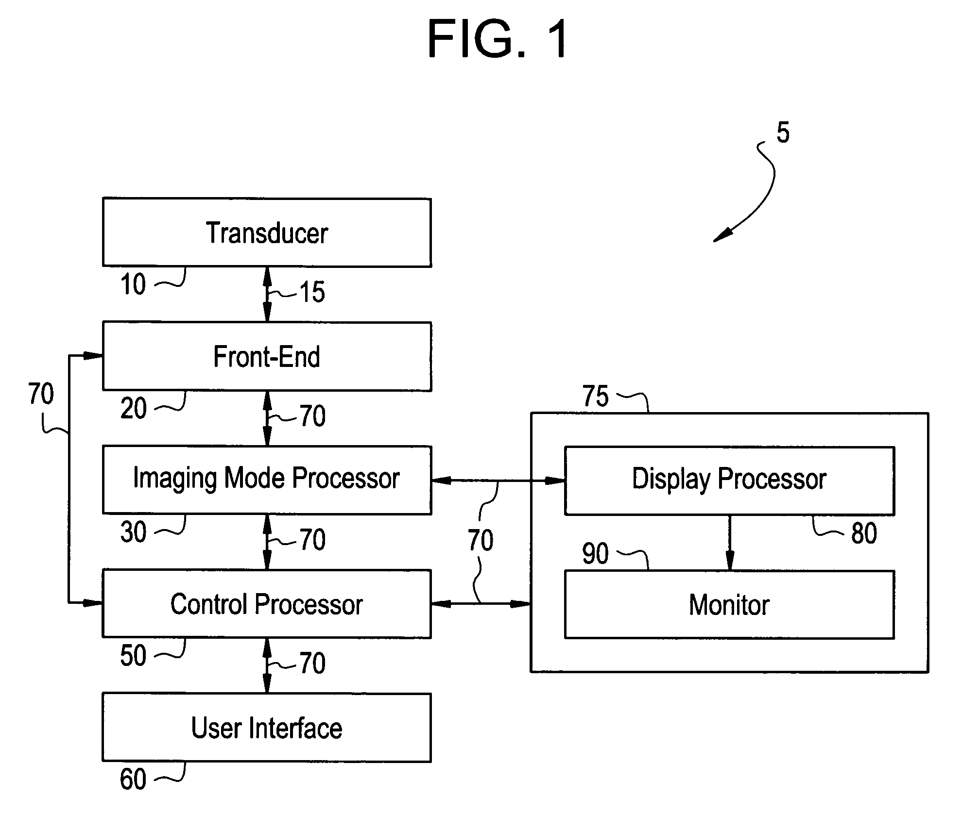
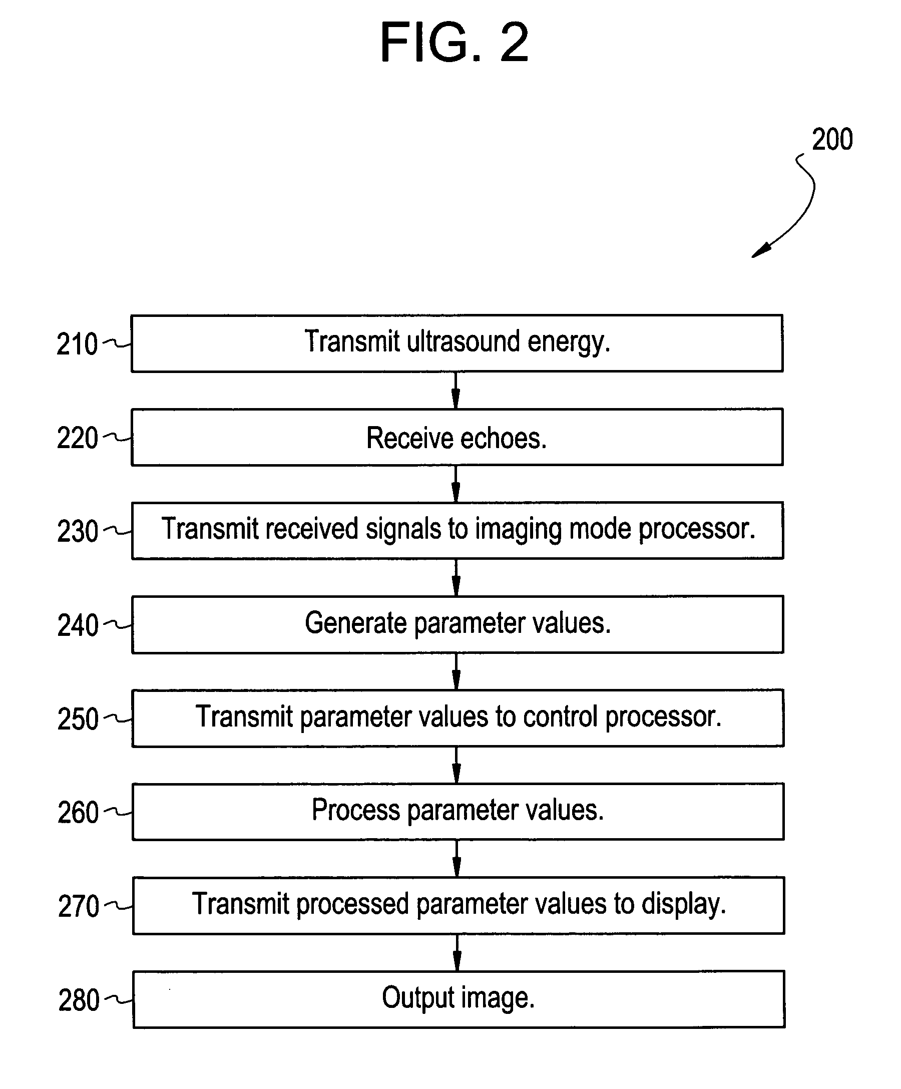
[0024]FIG. 1 illustrates a block diagram of an ultrasound imaging system 5 used in accordance with an embodiment of the present invention. The system 5 includes a transducer 10, a front-end 20, an imaging mode processor 30, a user interface 60, a control processor 50, and a display 75. The imaging mode processor 30 and the control processor 50 may be part of a back-end system, for example. The transducer 10 is used to transmit ultrasound waves into a subject by converting electrical analog signals to ultrasonic energy. The transducer 10 may also be used to receive ultrasound waves that are backscattered from the subject by converting ultrasonic energy to analog electrical signals. The front-end subsystem 20, including a receiver, a transmitter, and a beamformer, is used to create transmitted waveforms, beam patterns, receiver filtering techniques, and demodulation schemes that are used for various imaging modes. The front-end 20 converts digital data to analog data and vice versa. T...


PUM


Abstract

Certain embodiments of the present invention provide a method and system for real-time motion correction in compound ultrasound imaging. Certain embodiments include receiving an image frame, estimating motion between the image frame and a previous image frame, updating a previous motion estimate with the estimated motion to form an updated motion estimate, and correcting the image frame and the previous image frame using the updated motion estimate. The method may also include forming a compound image from the image frames. In an embodiment, motion may be estimated between the image frame and a previous frame using cross correlation, reference point registration, and / or other estimation method, for example. The image frame and the previous image frame may be corrected using the updated motion estimate in an affine transformation or other correction method, for example. In an embodiment, the method provides real-time correction as image frames are being received.

Description

RELATED APPLICATIONS[0001]Not ApplicableFEDERALLY SPONSORED RESEARCH OR DEVELOPMENT[0002]Not ApplicableMICROFICHE / COPYRIGHT REFERENCE[0003]Not ApplicableBACKGROUND OF THE INVENTION[0004]The present invention generally relates to ultrasound imaging. In particular, the present invention relates to real-time motion correction for ultrasound spatial compound imaging.[0005]Ultrasound is sound having a frequency that is higher than a normal person may hear. Ultrasound imaging utilizes ultrasound waves or vibrations in the frequency spectrum above normal human hearing, such as the 2.5-10 MHz range. Ultrasound imaging systems transmit ultrasound into a subject, such as a patient, in short bursts. Echoes are reflected back to the system from the subject. Diagnostic images may be produced from the echoes. Ultrasound imaging techniques are similar to those used in sonar and radar.[0006]A medical ultrasound system forms an image by sequentially acquiring echo signals from ultrasound beams trans...

Claims


Application Information

Patent Timeline
Patent Type & Authority Patents(United States)
IPC IPC(8): G06K9/00
CPCA61B8/00A61B8/5276G03B42/06A61B8/08
Inventor LIN, FENG
Owner GENERAL ELECTRIC CO
Learn More