Buoyancy control systems and methods for submersible objects

Active Publication Date: 2011-12-06
EXOCETUS DEV LLC
View PDF4 Cites 31 Cited by
  • Summary
  • Abstract
  • Description
  • Claims
  • Application Information

AI Technical Summary

Benefits of technology

[0016]The present invention may be embodied as a buoyancy control system comprising a housing, a first piston, and a second piston. The first and second pistons are movably supported by the housing. In a sh

Problems solved by technology

One problem with the “internal bladder / external bladder” class of buoyancy engine is that a large amount of fluid is required to adjust the buoyancy of the device.
The ratio of required fluid to potential displacement limits the net buoyancy of the vehicle.
In the context of gliders, this limitation on net buoyancy limits the speed of the glider and also the ability of the glider to adjust its buoyancy in response to changes in salinity and temperature.
Another disadvantage of the “internal bladder / external bladder” buoyancy engine is that the hydraulic pumps used in these designs are typically optimized for maximum efficiency at a significantly higher pressure than the operational pressure of the device.
In particular, the hydraulic pump does not operate at maximum efficiency at the maximum operational depth of the vessel, and the hydraulic pump is even less efficient at shallower depths.
The “ball screw / piston” type of buoyancy engine similarly suffers from low efficiency.
In addition, the ball screw assembly itself typically operates at only about 95% efficiency, thereby reducing the maximum potential efficiency of this system to a range of 50-60%.

Method used


Image

  • Buoyancy control systems and methods for submersible objects
  • Buoyancy control systems and methods for submersible objects
  • Buoyancy control systems and methods for submersible objects

Examples


Embodiment Construction

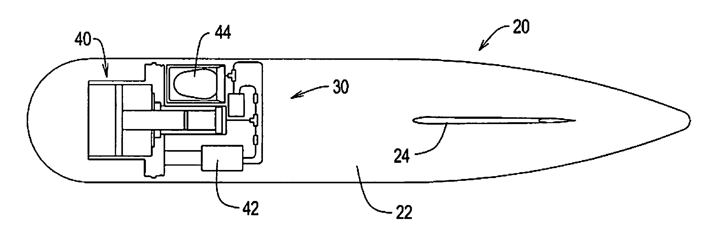
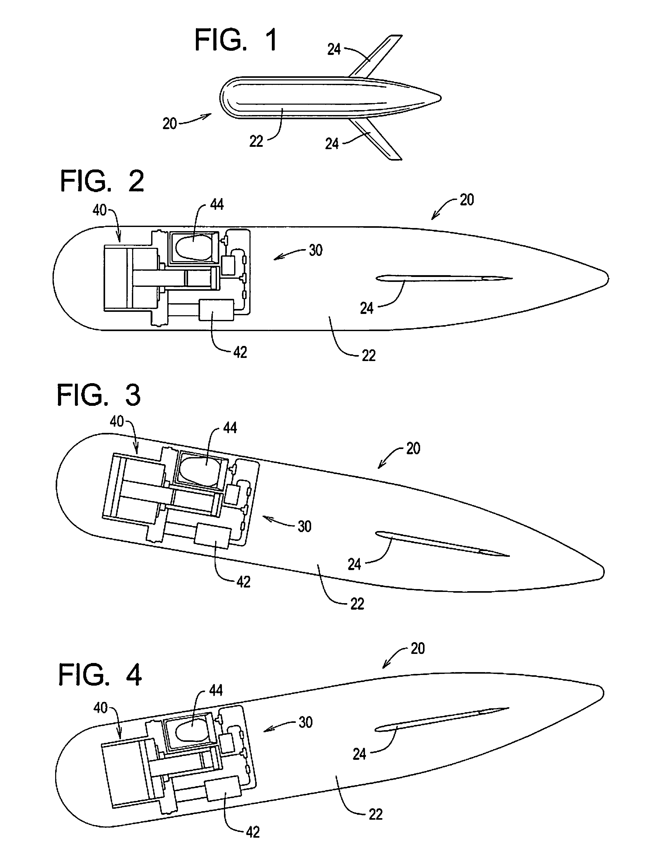
[0032]Referring initially to FIG. 1 of the drawing, depicted therein is an example waterborne vessel in the form of a glider 20. The example glider 20 is generally conventional in that it comprises a hull assembly 22 and one or more fins and / or wings 24. FIGS. 2-3 illustrate that the example glider 20 further comprises a buoyancy control system 30 arranged within the hull assembly 22.

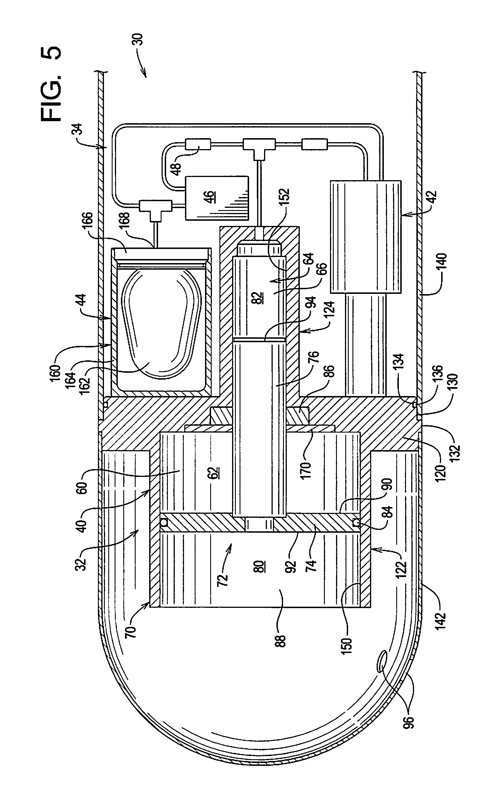
[0033]The buoyancy control system 30 is depicted in further detail in FIGS. 5-7 of the drawing. In particular, FIG. 5 illustrates details of a mechanical portion 32 of the buoyancy control system 30, while FIG. 6 schematically illustrates both the mechanical portion 32 and a control portion 34 of the buoyancy control system 30.

[0034]Referring initially to FIG. 6 of the drawing, it can be seen that the example mechanical portion 32 comprises a piston assembly 40, a pump assembly 42, an accumulator assembly 44, a valve assembly 46, and a filter 48. FIG. 6 further shows that the example control portion 34 ...


PUM


Abstract

A buoyancy control system comprises a housing and first and second pistons movably supported by the housing. In a shallow mode, displacement of the first piston alters a buoyancy of the buoyancy control system. In a deep mode, displacement of the first and second pistons alters the buoyancy of the buoyancy control system.

Description

RELATED APPLICATIONS[0001]This application is a continuation-in-part of pending U.S. patent application Ser. No. 12 / 345,182, filed Dec. 28, 2008.[0002]U.S. patent application Ser. No. 12 / 345,182 claims benefit of U.S. Provisional Application Ser. No. 61 / 009,364, filed on Dec. 26, 2007. The contents of the related applications listed in this paragraph are incorporated herein by reference.TECHNICAL FIELD[0003]The present invention relates to systems and methods for controlling the buoyancy of waterborne objects and, more specifically, to buoyancy control systems and methods for controlling the buoyancy of devices and vehicles that are capable of being submersed.BACKGROUND OF THE INVENTION[0004]The ability to control the buoyancy of an object is desirable in many applications. For example, in the field of unmanned underwater vehicles (UUVs), it is often desirable to adjust the buoyancy of the vehicle to stabilize it in the water column (hover) or to make the vehicle rise or sink within...

Claims


Application Information

Patent Timeline
IPC IPC(8): B63G8/14
CPCB63G8/22B63G8/24
Inventor IMLACH, JOSEPHFARLEY, PAUL J.DEVOLL, TRACY D.
Owner EXOCETUS DEV LLC
Why Eureka
Try Eureka