System and method for providing a dynamically configured low drop out regulator with zero quiescent current and fast transient response

a regulator circuit and low drop out technology, applied in the field of semiconductor circuit manufacturing, can solve the problems of low output voltage (vsub>cc/sub>) conflicting quiescent current and fast transient response, and low efficiency of the ldo circui

Active Publication Date: 2011-12-06
NAT SEMICON CORP
View PDF22 Cites 41 Cited by
  • Summary
  • Abstract
  • Description
  • Claims
  • Application Information

AI Technical Summary

Benefits of technology

[0026]It is an object of the present invention to provide a system and method for providing an improved power supply control circuit that remedies deficiencies that are present in prior art power supply control circuits.
[0027]It is also an object of the present invention to provide a system and method for providing an improved power supply control circuit that can dynamically operate a low drop out regulator circuit.

Problems solved by technology

But an LDO circuit will have a very low efficiency when its output voltage (VCC) is very low compared with its input voltage (VBATT).
However, these two desirable requirements (low quiescent current and fast transient response) are in conflict with each other.

Method used


Image

  • System and method for providing a dynamically configured low drop out regulator with zero quiescent current and fast transient response
  • System and method for providing a dynamically configured low drop out regulator with zero quiescent current and fast transient response
  • System and method for providing a dynamically configured low drop out regulator with zero quiescent current and fast transient response

Examples


Embodiment Construction

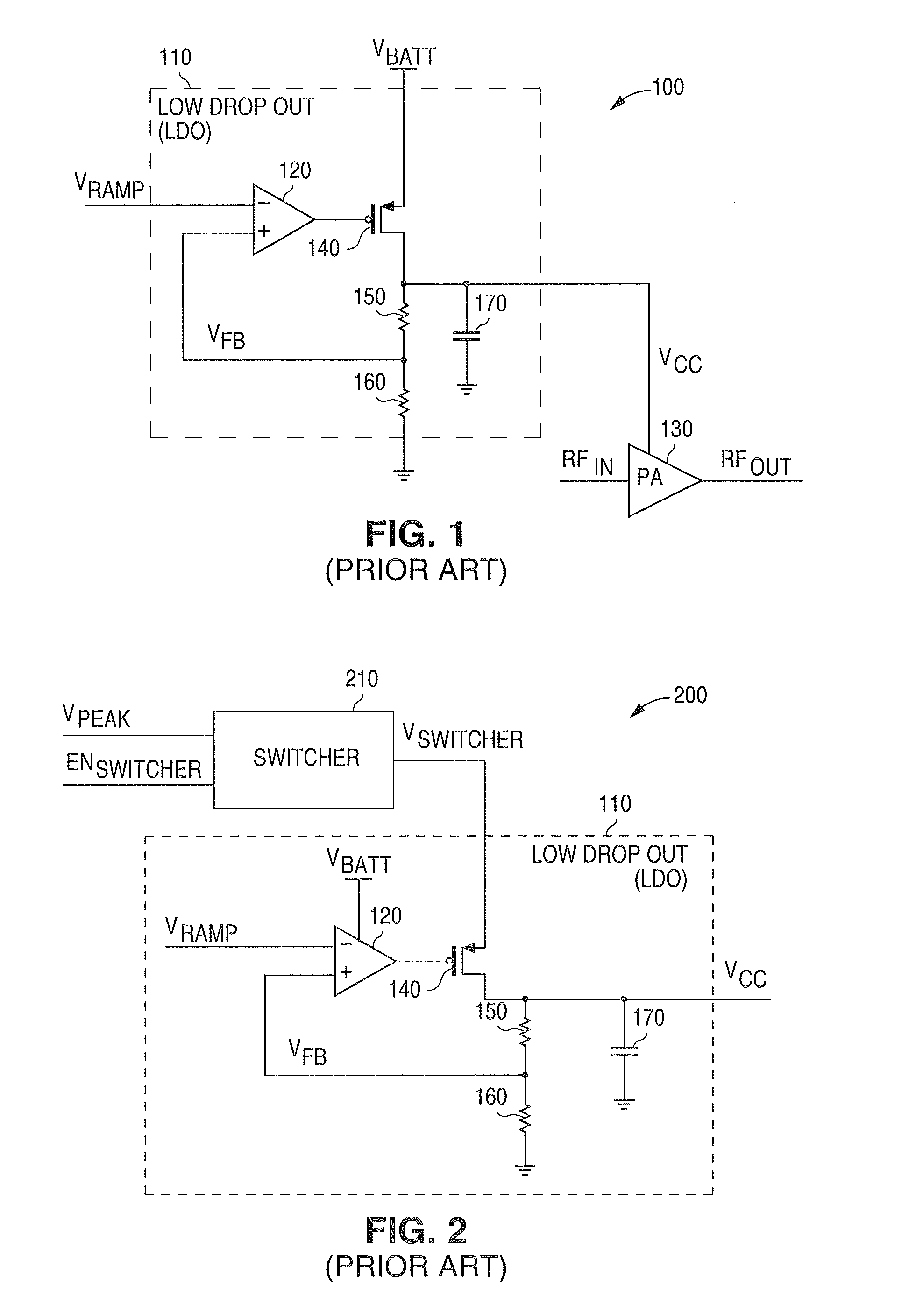
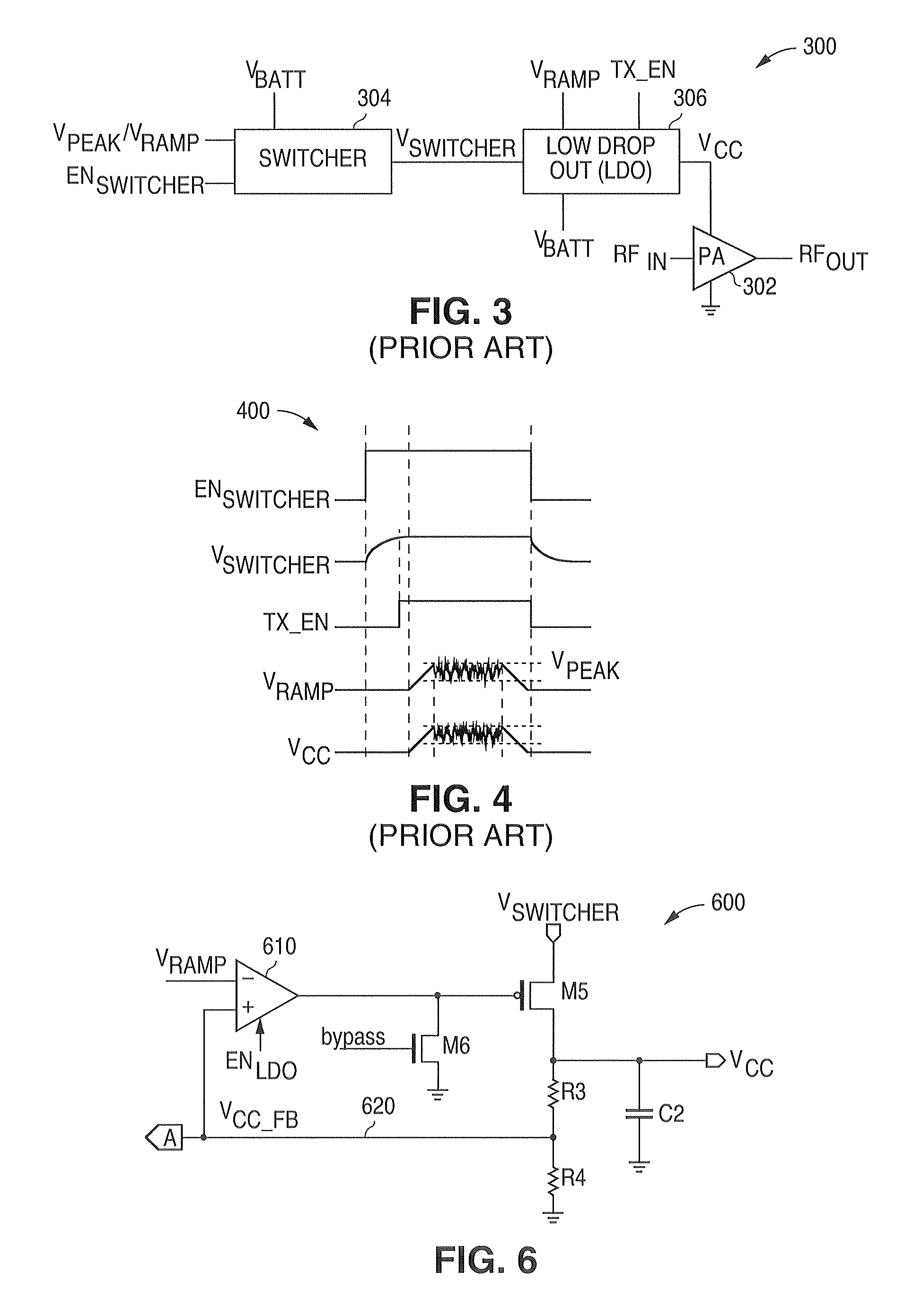
[0042]FIGS. 1 through 8 and the various embodiments used to describe the principles of the present invention in this patent document are by way of illustration only and should not be construed in any way to limit the scope of the invention. Those skilled in the art will understand that the principles of the present invention may be implemented in any type of suitably arranged power amplifier circuit.

[0043]To simplify the drawings the reference numerals from previous drawings will sometimes not be repeated for structures that have already been identified.

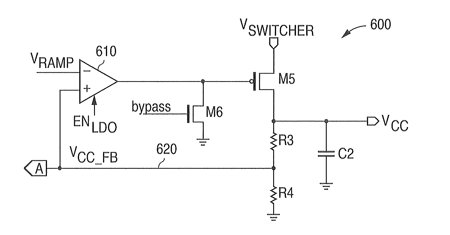
[0044]The present invention (1) uses the low drop out (LDO) regulator when a fast transient response is needed and (2) completely shuts down the operation of the low drop out (LDO) regulator when the power supply control voltage VCC is in a steady state condition. The manner in which these steps are accomplished will be described more fully below.

[0045]An advantageous embodiment of a power supply control circuit of the present invent...


PUM


Abstract

A system and a method are disclosed for providing a dynamically configured low drop out regulator that has zero quiescent current and a fast transient response. A power supply control circuit is provided that comprises a switcher circuit and a low drop out regulator and a control signal circuit. When the output voltage of the low drop out regulator is in a steady state condition the control signal circuit generates control signals that turn off the operation of the low drop out regulator to provide zero quiescent current. When the output voltage is not in a steady state condition the control signal circuit generates control signals that turn on the operation of the low drop out regulator to provide a fast transient response.

Description

CROSS-REFERENCE TO RELATED APPLICATION[0001]The present invention is related to an invention described and claimed in a patent application entitled “System and Method for Suppressing Load Transients in Radio Frequency Power Amplifier Switching Power Supplies” filed on the same date of the present patent application and assigned to the assignee of the present patent application as patent application Ser. No. 12 / 008,843.TECHNICAL FIELD OF THE INVENTION[0002]The present invention is generally directed to the manufacture of semiconductor circuits and, in particular, to a system and method for providing a dynamically configured low drop out regulator circuit.BACKGROUND OF THE INVENTION[0003]The telecommunications industry continually attempts to improve the transmitter circuitry in wireless communication systems. Power amplifier (PA) circuitry is a major component of a transmitter of a wireless communication device. Power amplifier (PA) circuitry provides the power for transmitting a sig...

Claims


Application Information

Patent Timeline
Patent Type & Authority Patents(United States)
IPC IPC(8): G05F1/563G05F1/595
CPCG05F1/56H02M3/1588H02M2001/0045Y02B70/1466H02M1/0045Y02B70/10
Inventor LI, YUSHAN
Owner NAT SEMICON CORP
Why Eureka
Try Eureka