Haptic solenoid system

a solenoid and haptic technology, applied in the field of haptic solenoid systems, can solve problems such as vibration, and achieve the effect of saving cost and efficient operation

Active Publication Date: 2011-12-06
JOHNSON ELECTRIC SA
View PDF4 Cites 10 Cited by
  • Summary
  • Abstract
  • Description
  • Claims
  • Application Information

AI Technical Summary

Benefits of technology

[0005]The main object of the present invention is to provide a haptic solenoid and a haptic solenoid system particularly adapted for automotive use for providing touch / sensory feedback to a user when a virtual button is depressed on a monitor or display screen mounted in an automobile. This feedback combined with software technology will allow automotive manufacturers to eliminate push buttons on the dashboard and thus save cost. This invention covers a novel haptic solenoid and system combinations including the haptic solenoid, but not the software technology that drives it. The main advantages for the haptic solenoid of the present invention lie in the unique design of the frame for the haptic solenoid, which enables efficient operation and quick and cost effective installation to a base support and to a touch screen.
[0008]As will be appreciated from the foregoing, the purpose of the present invention is to produce short bursts of vibrational energy / motion that can be sensed by tactile feel.
[0009]The principal uses of the invention include tactile feedback actuation for touch screens in place of physical selector buttons in vehicles, tactile actuation in a seat or chair in an automobile to improve alertness / safety, and other like applications.
[0010]The haptic solenoid can be used without any noise suppression of the plunger movement, if the haptic solenoid is being used in a noisy environment. However, for a quiet environment, such as, an automobile, it is important that noise be suppressed. This is accomplished through the use of a bumper on one or both poles of the solenoid. The bumper can be a simple narrow annular resilient bumper, a bumper with skirt design to allow more surface area of the pole to be protected with acoustic dampening material or preferably a bumper of skirt design with novel cutouts. Additionally, the poles can be provided with notches to hold the bumpers in position and prevent any movement of the bumpers during use. Preferably the bumper attachment notches in the poles are located out of the direct path of the field to not adversely affect the acceleration. Also, bumpers with skirts can be designed with thinner skirt material between adjacent pole portions so that an optimum gap (spacing) between the poles can be maintained.

Problems solved by technology

During operation, the vibration induced by the poles of the solenoid is transferred by the plastic frame to the touch screen frame causing its vibration.

Method used


Image

  • Haptic solenoid system
  • Haptic solenoid system
  • Haptic solenoid system

Examples


first embodiment

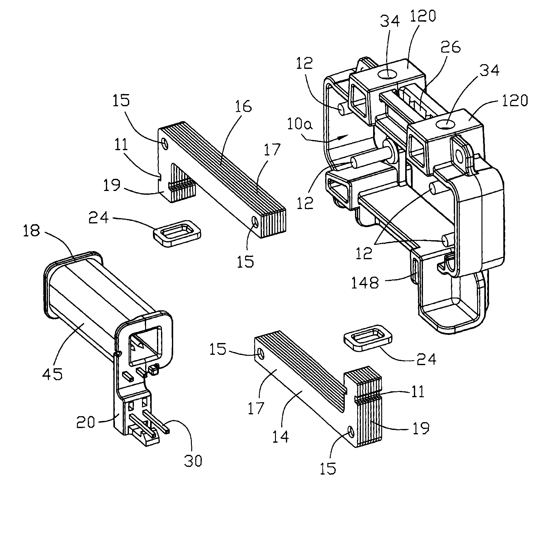
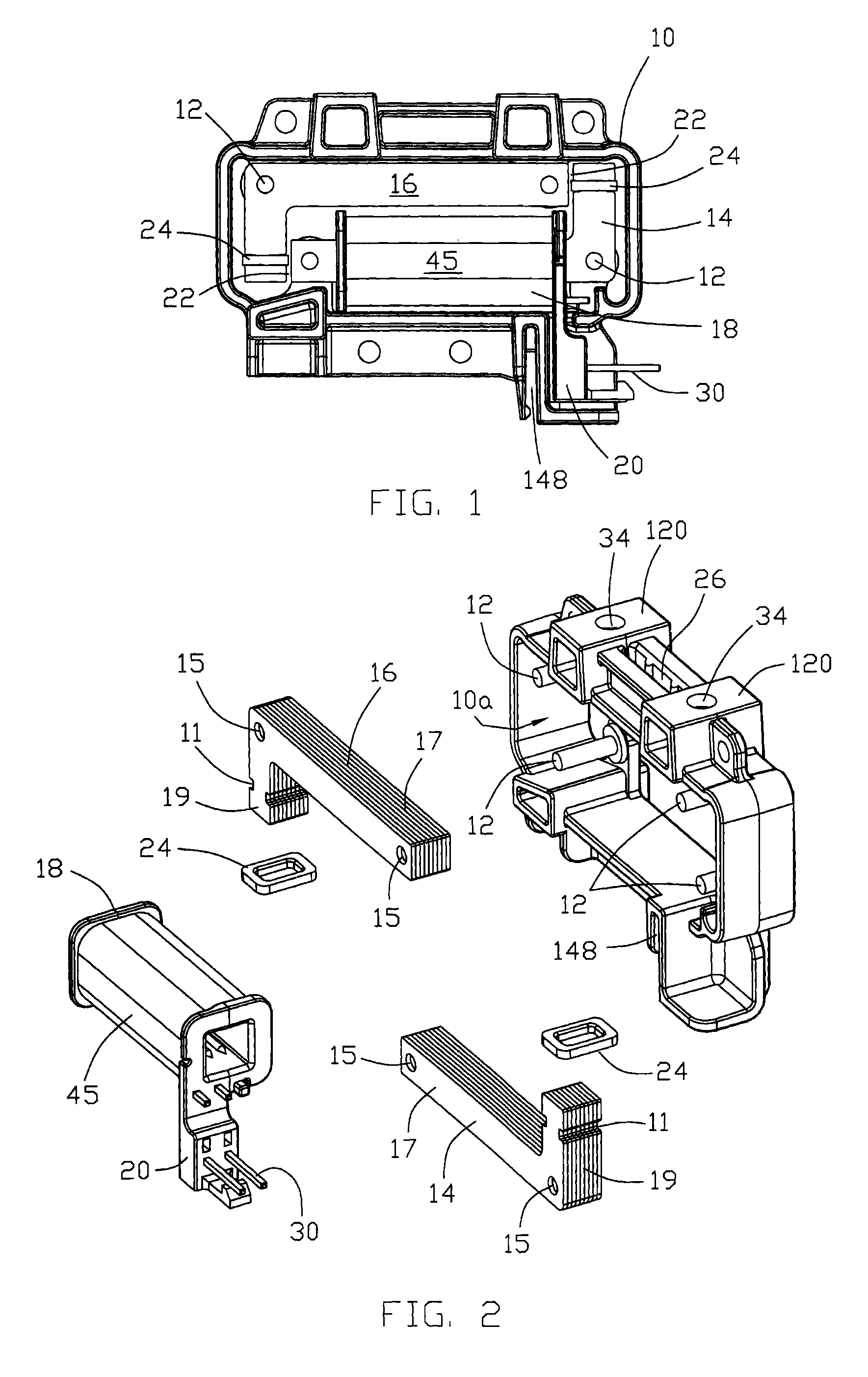
[0034]Referring now to the drawings, FIGS. 1 and 2 shows the novel haptic solenoid. The solenoid consists of a quadrilateral plastic frame 10, rectangular in longitudinal cross section that is hollow or has a central through opening or open area 10a. Poles 14 and 16 and all other components are secured to frame 10, which provides return flex to create the vibration feel. Frame 10 is mounted on a supporting plate, as will be explained in detail hereinafter, and remains in a stationary orientation, and its top portion will flex, as also shall be described in detail hereinafter.

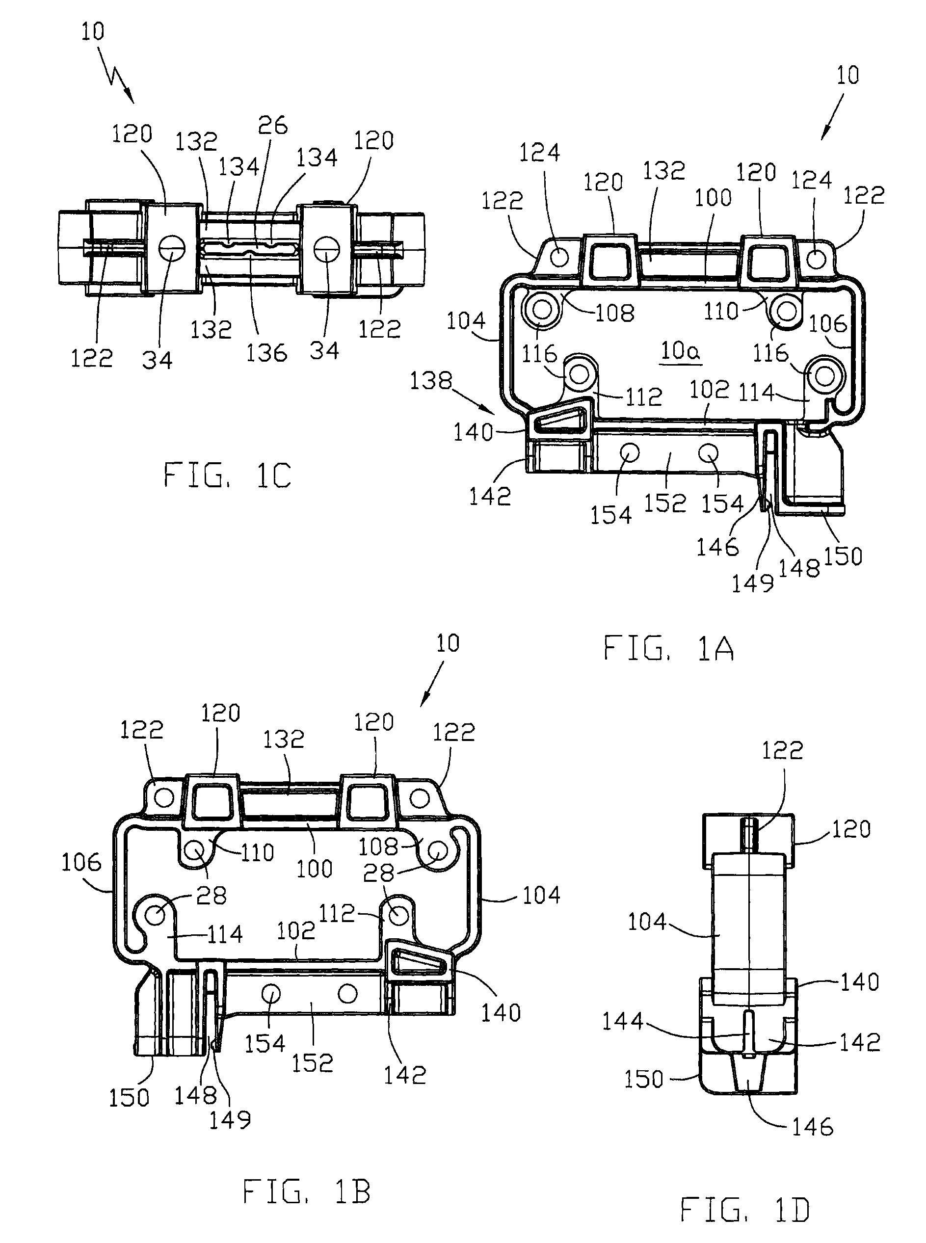
[0035]Referring now to FIGS. 1A to D, the frame 10 will now be described in more detail. FIG. 1A shows frame 10 in front elevation. The use of “front”, “back”, “upper”, “lower”, “left”, “right”, etc is simply for reference and convenience in describing the frame 10 and not in any way for limitation. Frame 10 can assume any orientation relative to its contacting structure depending on how it is mounted to its sup...

third embodiment

[0056]the present invention, and the best mode for carrying out the invention as contemplated by the inventors, utilizes two bumpers 80, as shown in FIGS. 13 and 14, in place of bumpers 25. Bumper 80 is essentially like bumper 25, that is, annular, square in cross section and resilient with a flat top 82 that extends outwardly on first opposite sides and an integral depending skirt 84, which has cutouts 86 on second opposed sides created by removing a portion of the side just beneath the flat top 82 which allows for gap control during assembly. One second opposed side is located in gap 22. The skirt also has hemispherical cutouts 88 on the first opposed bottom edges 88a of the skirt 84 that assist during assembly vis-à-vis the pole flat surfaces. Thus, the cutouts 88 on the first opposed sides are displaced ninety degrees from the side cutouts 86 on the second opposed sides. Otherwise the components of the haptic solenoid are the same as in the first two embodiments.

[0057]For automo...


PUM


Abstract

A supporting surface and a touch screen member mounted to a plastic frame having a first vibration transmitting slot and at least two mounting slots. A pair of similar L-shaped poles is mounted in the frame in juxtaposition to define gaps between them. One of the poles constitutes a stationary pole and the other of the poles constitutes a movable pole. A winding is mounted on the stationary pole. The frame defines a vibration transmitting slot, and the touch screen member is attached to the frame by a tab that is press fitted into the vibration transmitting slot so that vibrations created by the movable pole can be transmitted via the vibration transmitting slot to the touch screen member. The additional slots defined by the frame and tabs defined by the supporting surface mutually coact for mounting the frame to the supporting member in a stationary position.

Description

BACKGROUND OF THE INVENTION[0001]1. Field of the Invention[0002]This present invention relates to a haptic solenoid and a haptic solenoid system to provide touch / sensory feedback to a user when a virtual button is depressed on a monitor or display screen, and more particularly, to a haptic solenoid system in an automobile environment.[0003]2. Prior Art[0004]Existing products for touch sense mainly available on the market include small motor devices that are used in cell phones and electronics / video games. Nothing is currently available or used in the automotive market. The main problem with existing products is that none are available or adapted for automotive markets. Also, haptic solenoids are known, but a problem with known designs is that during the short bursts of vibrational energy / motion, an audible clicking noise may be heard. Whereas in a noisy installation this would not be a problem, in an automobile this noise is undesirable as it can interfere with user chosen electroni...

Claims


Application Information

Patent Timeline
Patent Type & Authority Patents(United States)
IPC IPC(8): G08B6/00
CPCH02K3/50H02K33/02H01H2215/05H02K5/225H02K5/08
Inventor SPROELICH, APARNA MISHRARAWLS, DAVIDHILLIARD, DOUG
Owner JOHNSON ELECTRIC SA
Why Eureka
Try Eureka