
Method and system for structured DMA transactions

Active Publication Date: 2011-12-13
MICROSOFT TECH LICENSING LLC
View PDF19 Cites 1 Cited by
  • Summary
  • Abstract
  • Description
  • Claims
  • Application Information

AI Technical Summary

Benefits of technology

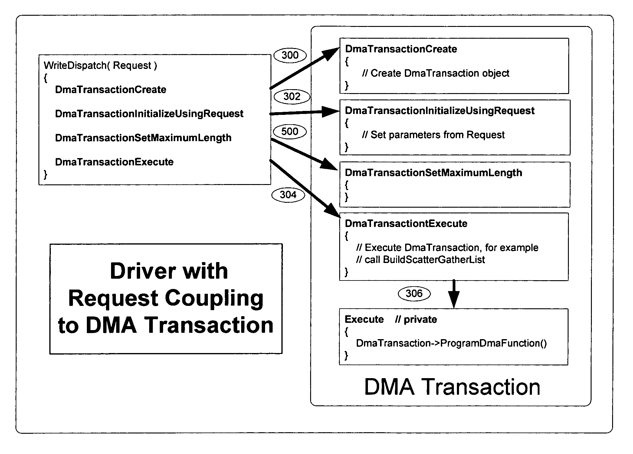
[0006]In view of the foregoing, the present invention provides a structured model for developing DMA code and for performing DMA transactions. This model of structured DMA transactions lessens the burdens on DMA software developers by providing a framework with default behaviors. Developers need only provide a minimal amount of configuration information and can then characterize subsequent DMA transactions in terms of a profile, thus reducing the amount of detailed and often redundant information that developers need to provide for each DMA transaction. If necessary, the developer can choose to override the profile for a specific DMA transaction.

Problems solved by technology

Because DMA transactions proceed asynchronously with respect to a device's CPU, and because more than one of these asynchronous transactions may be in process at the same time, coordinating DMA transactions is quite complicated and often confusing.
Some confusion arises because different operating systems impose different requirements on software developers who write code for DMA transactions.
These developers may have only incomplete knowledge of the DMA requirements and capabilities of a device.
Also, the developers may have neither the time nor the inclination to master all of the details of a given device's DMA transactions.
Code supporting DMA transactions is thus implemented in an ad hoc fashion which invites errors and inefficiencies and which does not provide a stable basis for future development.
The resulting situation is that DMA transactions often run at a level of efficiency lower than would otherwise be possible, and ill formed DMA transactions can slow down or even jeopardize the stability of computing systems.

Method used


Image

  • Method and system for structured DMA transactions
  • Method and system for structured DMA transactions
  • Method and system for structured DMA transactions

Examples


Embodiment Construction

[0021]Turning to the drawings, wherein like reference numerals refer to like elements, the present invention is illustrated as being implemented in a suitable computing environment. The following description is based on embodiments of the invention and should not be taken as limiting the invention with regard to alternative embodiments that are not explicitly described herein.

[0022]In the description that follows, the environment surrounding the present invention is described with reference to acts and symbolic representations of operations that are performed by one or more computing devices, unless indicated otherwise. As such, it will be understood that such acts and operations, which are at times referred to as being computer-executed, include the manipulation by the processing unit of the computing device of electrical signals representing data in a structured form. This manipulation transforms the data or maintains them at locations in the memory system of the computing device,...


PUM


Abstract

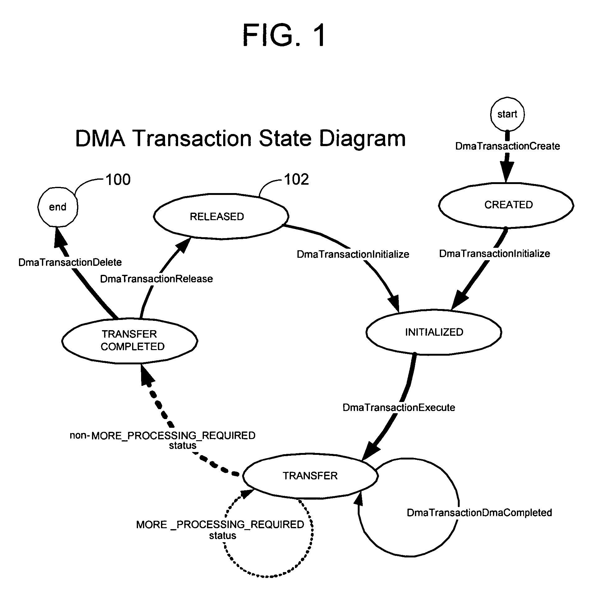
Disclosed is a structured model for developing DMA code and for performing DMA transactions. This model of structured DMA transactions provides a framework with default behaviors. Developers need only provide a minimal amount of configuration information and can then characterize subsequent DMA transactions in terms of a profile, thus reducing the amount of detailed and often redundant information that developers need to provide for each DMA transaction. In some embodiments, the DMA transaction model is expressed in terms of object-oriented programming constructs. In one example, a DMA enabler object captures general DMA operational parameters and manages underlying operating system objects and behavior. When device manager software receives an input / output request that involves a DMA data transfer, the device manager constructs a DMA transaction object that represents the DMA work request. During the processing of the DMA transaction, the DMA transaction object maintains state and status information.

Description

CROSS-REFERENCE TO RELATED APPLICATION[0001]The present application is related to U.S. patent application Ser. No. 10 / 985,174, entitled “Method and System for Structured Programmed Input / Output Transactions”, filed on Nov. 10, 2004.TECHNICAL FIELD[0002]The present invention is related generally to direct memory access (DMA) transactions in computing systems, and, more particularly, to structured DMA transactions.BACKGROUND OF THE INVENTION[0003]DMA is a set of techniques for moving data from one area of memory in a computing device to another area. DMA transactions are very efficient because, once a DMA transfer operation is configured, it does not further involve the central processing unit (CPU) of the computing device, allowing the CPU to do other work while the DMA transaction proceeds. DMA transactions have thus become common and often essential features of modern computing devices.[0004]Because DMA transactions proceed asynchronously with respect to a device's CPU, and because...

Claims


Application Information

Patent Timeline
IPC IPC(8): G06F3/00G06F13/28G06F13/36
CPCG06F13/28
Inventor CALLENDER, ROBIN L.
Owner MICROSOFT TECH LICENSING LLC
Learn More