Slide type continuous variable valve lift device

a technology of continuous variable valve and lift device, which is applied in the direction of machines/engines, engine components, mechanical apparatus, etc., can solve the problems of increasing the number of springs, difficult to precisely operate, and large amount of power loss, so as to reduce the number of parts, and reduce the effect of power loss

Inactive Publication Date: 2011-12-20
HYUNDAI MOTOR CO LTD
View PDF7 Cites 1 Cited by
  • Summary
  • Abstract
  • Description
  • Claims
  • Application Information

AI Technical Summary

Benefits of technology

[0021]Various embodiments of the present invention provide a slide type continuous variable valve lift (CVVL) device that may minimize the number of places where sliding friction between respective parts may occur so as to minimize power loss and enable more precise operation control as well as reduce the number of parts so as to enhance the overall robustness of the device.
[0035]According to various embodiments of the present invention, the CVVL device can reduce the number of places where sliding friction between respective parts may occur to minimize power loss and enable more precise operation control, reduce the number of parts so as to enhance the overall robustness of the device, and advance the time of maximum valve opening so as to improve the fuel efficiency of an engine.

Problems solved by technology

A large amount of power is lost by friction, and thus precise operation control becomes difficult.
Other problems include increasing the number of springs, which apply an elastic force to respective parts in order to constantly maintain the coupling positions of the respective parts, and increasing loss of friction of the respective parts
Furthermore, the friction loss of the respective parts is increased greatly due to the increased number of springs, which apply an elastic force to respective parts to constantly maintain the coupling positions of the respective parts.
Moreover, since the conventional CVVL device is made up of a large number of parts, it is difficult to fabricate the device, manufacturing costs are increased, and the overall robustness of the device becomes lower.

Method used


Image

  • Slide type continuous variable valve lift device
  • Slide type continuous variable valve lift device
  • Slide type continuous variable valve lift device

Examples


Embodiment Construction

[0045]Reference will now be made in detail to various embodiments of the present invention(s), examples of which are illustrated in the accompanying drawings and described below. While the invention(s) will be described in conjunction with exemplary embodiments, it will be understood that present description is not intended to limit the invention(s) to those exemplary embodiments. On the contrary, the invention(s) is / are intended to cover not only the exemplary embodiments, but also various alternatives, modifications, equivalents and other embodiments, which may be included within the spirit and scope of the invention as defined by the appended claims.

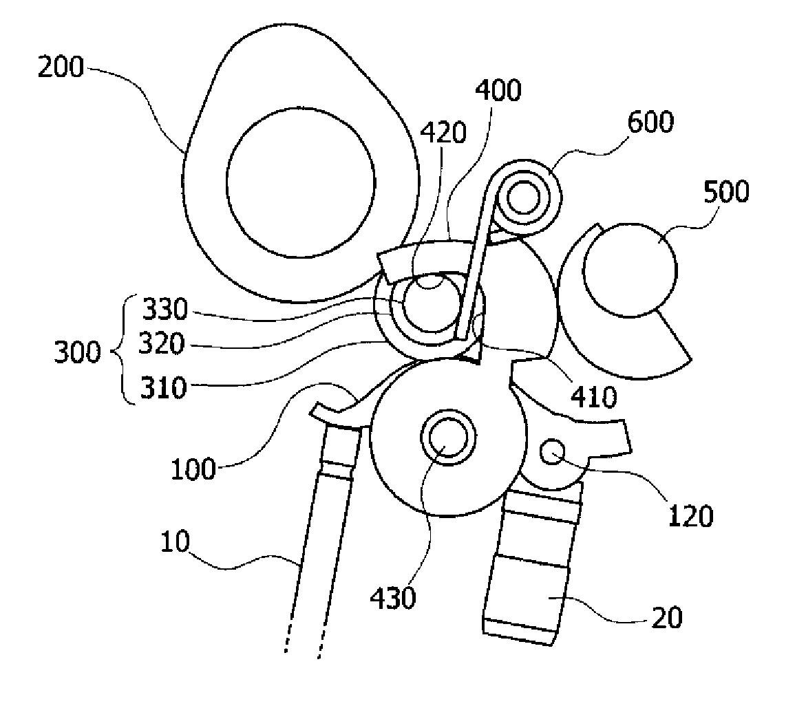
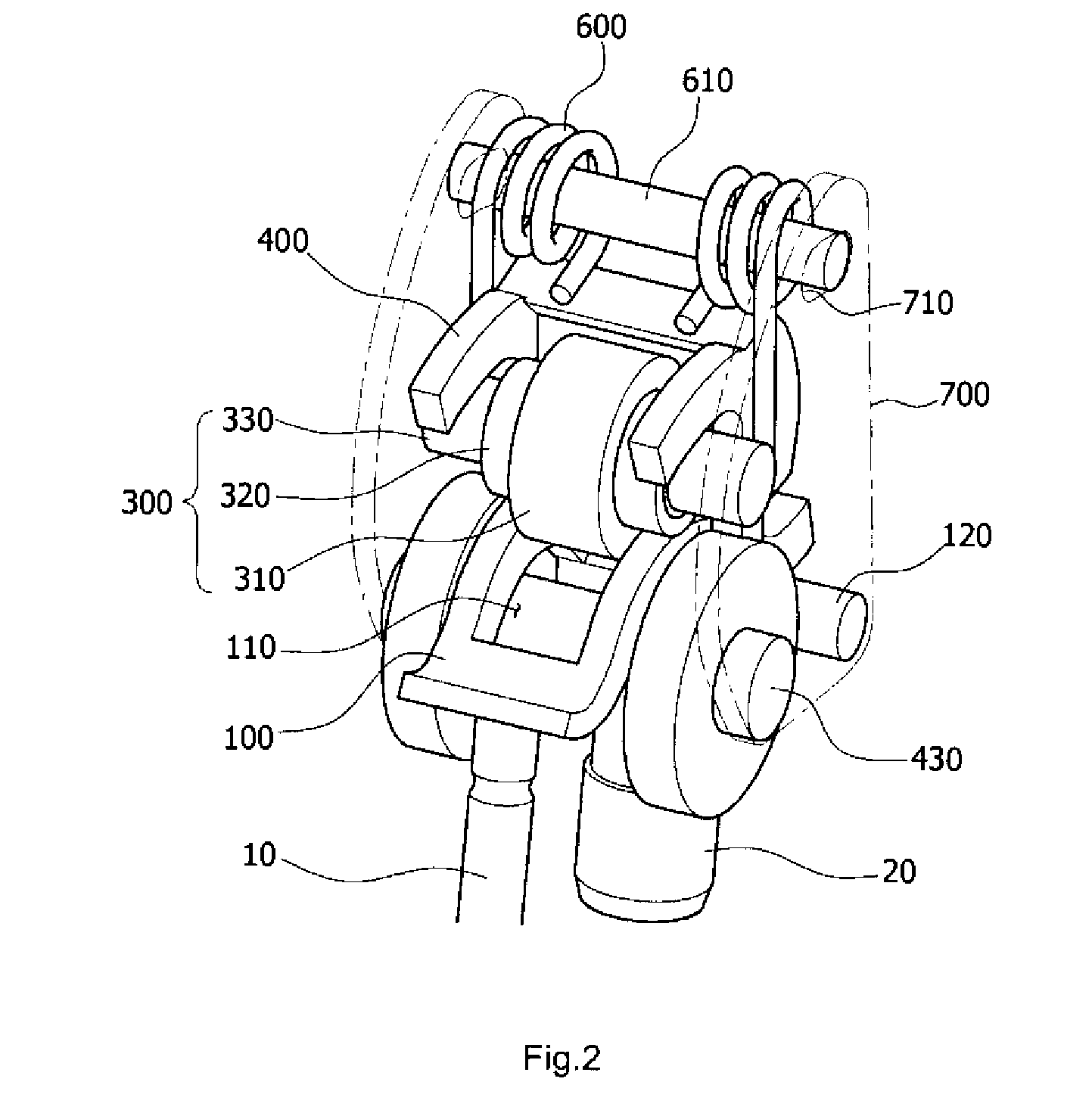
[0046]FIG. 2 is a perspective view illustrating a slide type CVVL device of the present invention. FIG. 3 is a side elevational view illustrating the slide type CVVL device of the present invention. FIGS. 4-6 are perspective views illustrating a swing arm, a roller and a guide of the slide type CVVL device of the present invention.

[00...


PUM


Abstract

A slide type continuous variable valve lift (CVVL) device includes a swing arm rotating to press a valve; a cam lobe; a roller transmitting a driving force of the cam lobe to the swing arm; and a guide guiding the roller to move along a predetermined path. The CVVL device generally can minimize the number of places where sliding friction between respective parts may occur to minimize power loss and enable more precise operation control, reduce the number of parts to enhance the overall robustness of the device, and advance the time of maximum valve opening to improve the fuel efficiency of an engine.

Description

CROSS-REFERENCE TO RELATED APPLICATION[0001]The present application claims the priority to Korean Patent Application No. 10-2008-0071695 filed Jul. 23, 2008, the entire contents of which application is incorporated herein for all purposes by this reference.BACKGROUND OF THE INVENTION[0002]1. Field of the Invention[0003]The present invention relates to a slide type continuous variable valve lift device.[0004]2. Description of Related Art[0005]As for an engine, a camshaft is rotated by a rotating force transmitted from a crank shaft, and an intake valve and an exhaust valve are reciprocated up and down with regular timing by cams of the camshaft. Thereby, intake air is supplied to a combustion chamber, and combustion gas is exhausted. In this process, a fuel-air mixture is compressed and exploded to generate power.[0006]At this time, a device that can continuously vary the lift distance of a valve according to an operating speed of the engine is called a continuous variable valve lift...

Claims


Application Information

Patent Timeline
Patent Type & Authority Patents(United States)
IPC IPC(8): F01L1/34
CPCF01L13/0026Y10T74/2107F01L13/00F01L1/18
Inventor CHOI, BYOUNG YOUNGPARK, DONG HEONBANG, SANG HYUN
Owner HYUNDAI MOTOR CO LTD
Why Eureka
Try Eureka