
Advanced firtree and broach slot forms for turbine stage 3 buckets and rotor wheels

a technology of turbine stage 3 and slot configuration, applied in the field of turbines, can solve the problem of each individual bucket being heavier, and achieve the effect of enhancing the load transfer

Active Publication Date: 2011-12-20
GENERAL ELECTRIC CO
View PDF17 Cites 8 Cited by
  • Summary
  • Abstract
  • Description
  • Claims
  • Application Information

AI Technical Summary

Benefits of technology

"The present invention provides an improved firtree / broach slot configuration for a high temperature turbine stage with 90 buckets. The new firtree form enhances the transfer of load from the bucket and firtree attachment to the wheel, reduces the pull force on the rotor wheel, and improves low and high cycle fatigue capabilities of both the bucket and the wheel. The new firtree form also reduces leaks across the stage and equalizes load transfer from the bucket to the wheelpost among the tangs. The reduced bucket count results in increased weight and circumferential length, which has been accounted for in the new firtree form. The new firtree form has unique dimensions and relationships between the bucket and wheel necessary for enhancing load transfer successfully. The new firtree form can be scaled to larger or smaller sizes and can be used in other applications where blades or buckets are attached to a rotating wheel or disk in a high temperature environment."

Problems solved by technology

However, a reduction in the number of buckets also results in each individual bucket being heavier as it covers a longer circumferential length.
Simply scaling the size of the buckets and slots on existing firtree and broach slot configurations, while maintaining the same size wheel, to reduce the number of buckets will not minimize the stresses acting at the attachment points.

Method used


Image

  • Advanced firtree and broach slot forms for turbine stage 3 buckets and rotor wheels
  • Advanced firtree and broach slot forms for turbine stage 3 buckets and rotor wheels
  • Advanced firtree and broach slot forms for turbine stage 3 buckets and rotor wheels

Examples


Embodiment Construction

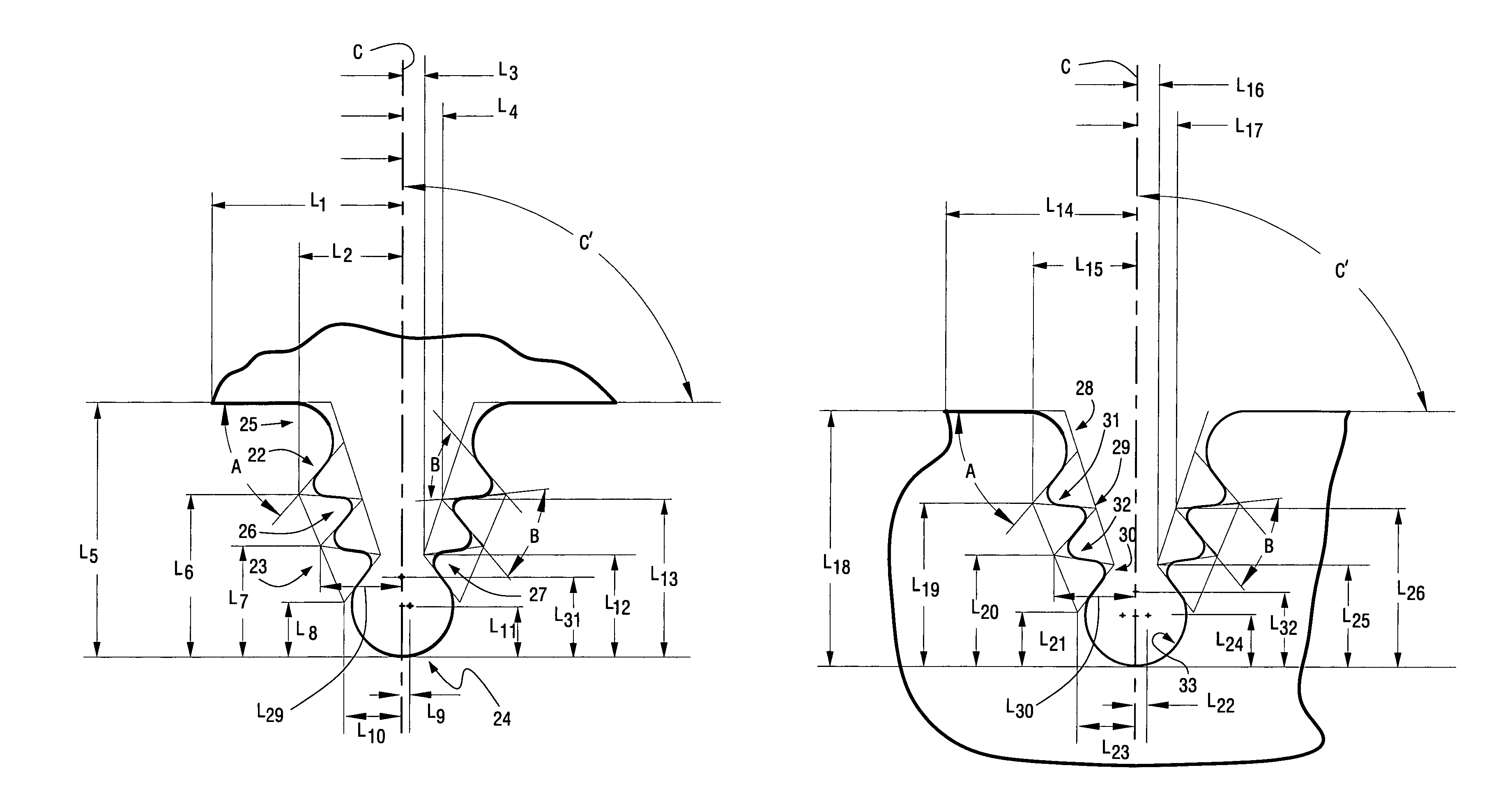
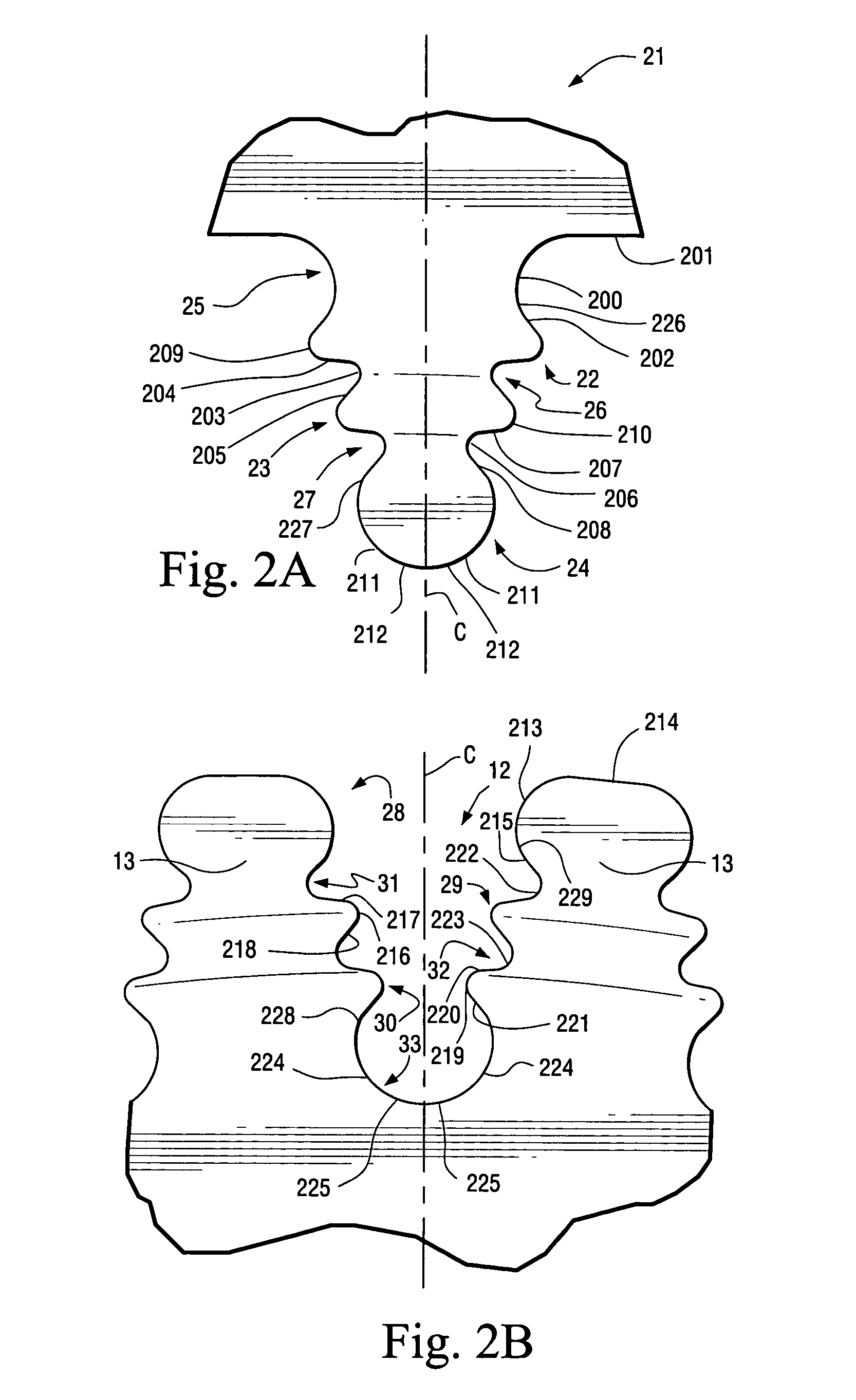
[0026]Key and fundamental elements of the invention are defined by two series of lines, arcs, and ellipses of which the adjacent components are tangent. One series depicts the profile or form of the firtree shape of the bucket root while the other series depicts the profile or form of the corresponding broach slot of the rotor wheel into which the firtree shape is fitted.

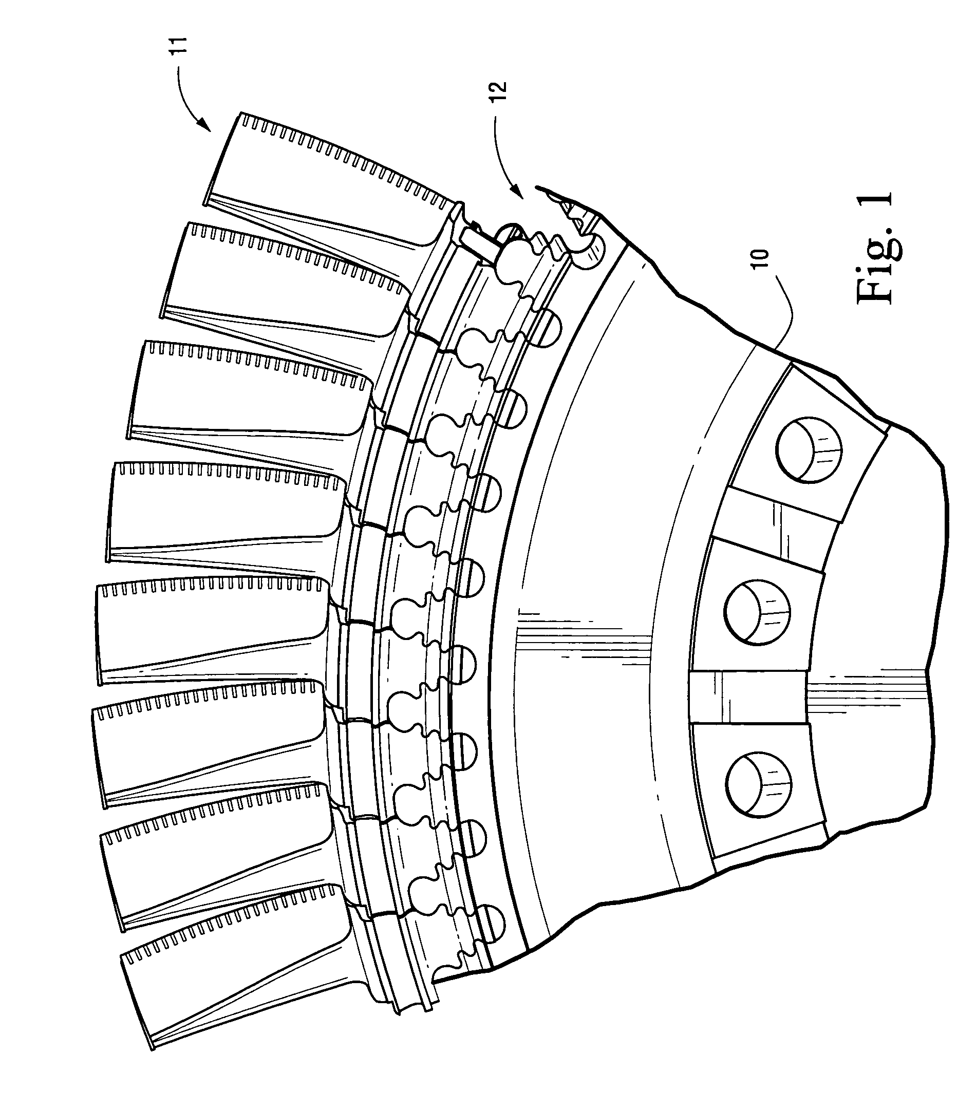
[0027]FIG. 1 shows a portion of an assembled rotor wheel 10 to include buckets 11 fitted into corresponding broach slots 12. Thus, the profile of the wheel broach slot 12 (best seen in the unfilled broach slot in FIG. 1) is substantially filled by the portion of the bucket 11 termed the bucket root (best seen by the filled wheel broach slot in FIG. 1).

[0028]FIG. 2A shows in cross-sectional schematic form the profile of bucket root 21 of bucket 11. Bucket root 21 comprises three sets of curved tangs 22, 23, 24 and three sets of fillets 25, 26, 27. One tang and fillet, from each set of tangs and fillets, is disposed o...


PUM


Abstract

A turbine bucket and wheelpost assembly reduces the number of buckets in the third stage of the turbine from ninety-two to ninety while reducing stresses at the assembly points of the buckets and wheelposts. The buckets and wheelposts are formed with complementary fillets and tangs that provide for the insertion of the bucket into the broach slot between two wheelposts. The angles of the fillets on both the bucket and wheelpost range from 50° to 59°. The upper surface of the wheelpost is scalloped to reduce weight and the tangs and fillets of both the bucket and wheelpost are formed from curved and straight surfaces to reduce stresses on the assembly.

Description

FIELD OF THE INVENTION[0001]The invention is directed to turbines and, more particularly, to an improved configuration for the root portion, known as a firtree, of a turbine bucket and the corresponding turbine wheel broach slot into which the bucket fits. More specifically, the present invention provides improved firtree / broach slot configurations that reduce the number of buckets required and the stresses acting on the buckets and wheel at the point of their attachment.BACKGROUND OF THE INVENTION[0002]The third stage of a typical gas turbine can have as many as 92 buckets that radially extend from a rotor or wheel. Each bucket has a root portion that is configured to mate with a corresponding broach slot in the wheel. The firtree / broach slot configurations are designed to reduce stresses that occur transiently and at normal operating speeds.[0003]Prior known firtree / broach slot configurations are disclosed in Goodwin, U.S. Pat. No. 4,260,331 issued on Apr. 7, 1981, Pisz et al., U....

Claims


Application Information

Patent Timeline
Patent Type & Authority Patents(United States)
IPC IPC(8): F01D5/30F01D5/02F01D9/02
CPCF01D5/3007F05D2220/3213F05D2220/321
Inventor LAGRANGE, BENJAMIN ARNETTELLOYD, TIMOTHY BRIAN
Owner GENERAL ELECTRIC CO
Learn More