
Exhaust dilution blower housing with remote air intake

a blower housing and remote air intake technology, applied in the direction of positive displacement liquid engines, piston pumps, lighting and heating apparatus, etc., can solve the problems of increasing the assembly cost of furnaces or water heaters, increasing the manufacturing cost, and increasing the time required for assembling the housing

Active Publication Date: 2011-12-20
REGAL BELOIT AMERICA
View PDF9 Cites 4 Cited by
  • Summary
  • Abstract
  • Description
  • Claims
  • Application Information

AI Technical Summary

Benefits of technology

The solution provides effective motor cooling and exhaust gas dilution while reducing noise and manufacturing costs, simplifying assembly and operation by isolating noise and heat, and ensuring safe handling.

Problems solved by technology

However, these modifications to the typical blower housing have complicated the constructions of the blower housing which increases their manufacturing cost.
In addition, the modifications to the typical blower housing have also complicated the assembly of the blower housing to the furnace or water heater with which it is used, resulting in increasing the time required to assemble the housing to the furnace or water heater and thereby increasing the assembly cost of the furnace or water heater.

Method used


Image

  • Exhaust dilution blower housing with remote air intake
  • Exhaust dilution blower housing with remote air intake
  • Exhaust dilution blower housing with remote air intake

Examples


first embodiment

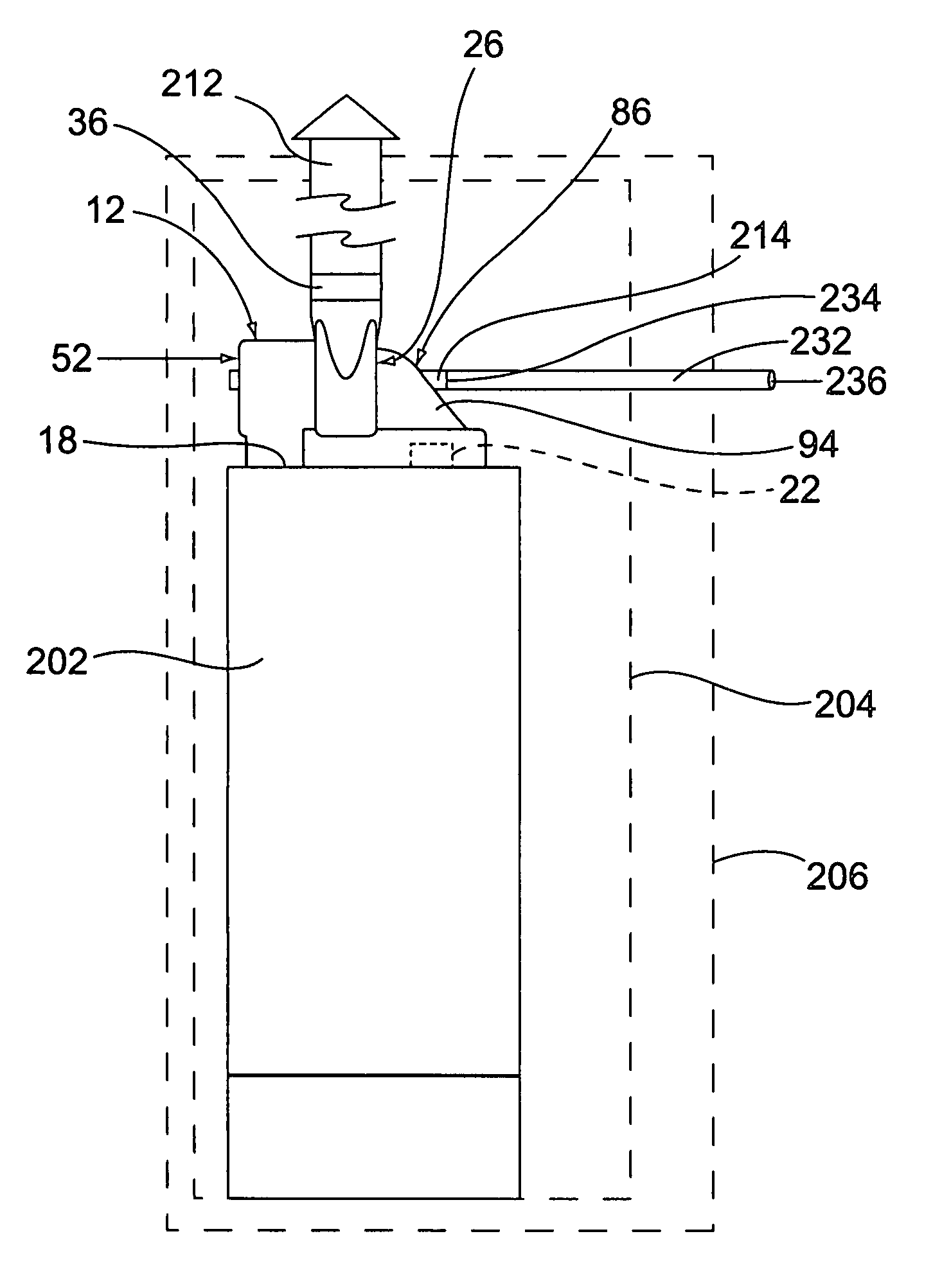
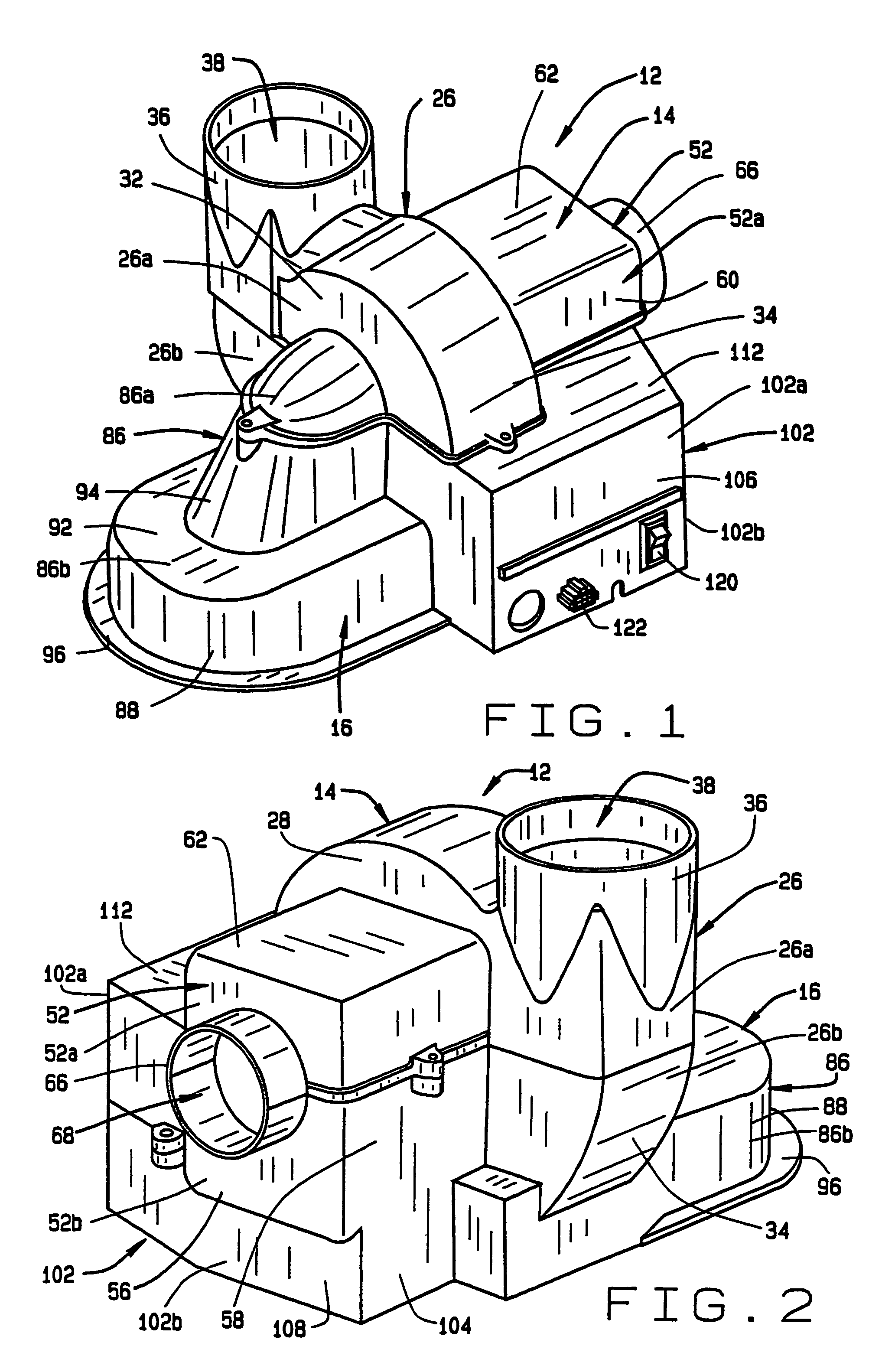
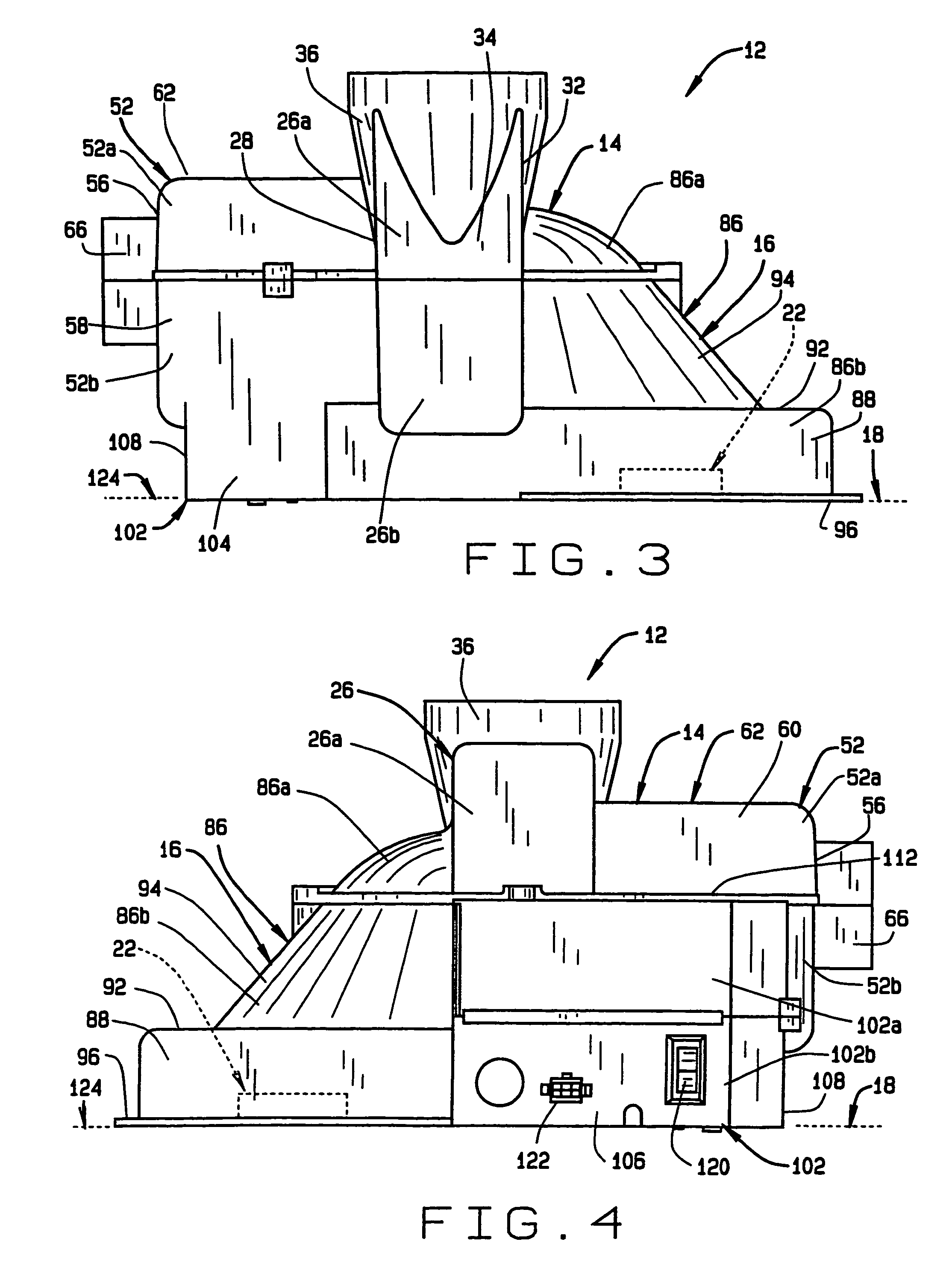
[0044]As shown in the drawing figures, the blower housing (12) of the present invention consists of two pieces including a first, top piece (14) and a second, bottom piece (16). The blower housing (12) is shown in FIGS. 1 and 2 mounted on top of a flat surface (18) of a furnace or water heater relative to the exhaust exit pipe (22) of the heater. Thus, describing the two pieces of the housing as a top piece and bottom piece describe only the relative positions of the two pieces when the housing is mounted on a top surface (18) of a heater. The blower housing (12) is equally well suited for mounting on the flat side surface of a furnace or water heater and therefore the terms “top” and “bottom” used in describing the two housing pieces should not be interpreted as limiting.

[0045]The blower housing is constructed with a fan compartment (26) that is enclosed between first and second end walls (28, 32) that are spaced from each other by a volute shaped side wall (34). The side wall (34)...

second embodiment

[0053]the blower housing (132) also includes a circuitry compartment (134) that extends below the motor compartment (52′). The circuitry compartment (134) also extends along portions of the side of the motor compartment (52′), the fan compartment (26′) and the dilution or exhaust compartment (86′) as seen in FIGS. 15, 17, and 18. Thus, portions of the walls of these compartments, in combination with a pair of opposite end walls (104′, 106′), and a side wall (108′) of the circuitry compartment enclose the interior of the compartment. As in the first described embodiment, the circuitry compartment (134) contains the electronic circuitry associated with the blower motor (78′) and isolates the circuitry from the fan compartment (26′), the motor compartment (52′) and the dilution / exhaust compartment (86′) except for the motor wiring hole (74′) and the pressure sensor opening (46′).

[0054]The circuitry compartment 134 of the second embodiment differs from that of the first embodiment in th...


PUM


Abstract

A blower housing may be used with a climate control furnace or with a water heater and provides cooling of the motor that rotates the blower fan and also provides dilution and cooling of exhaust gases drawn from the furnace or water heater. The housing has an interior dilution compartment that communicates with an elongate conduit. The dilution compartment receives dilution air through the conduit, thereby reducing blower operation noise at the blower housing.

Description

[0001]This patent application is a continuation-in-part of patent application Ser. No. 10 / 734,775, filed Dec. 12, 2003, which is currently pending, and which is a continuation-in-part of patent application Ser. No. 10 / 116,315 filed Apr. 4, 2002, which is currently pending now U.S. Pat. No. 6,827,560.BACKGROUND OF THE INVENTION[0002](1) Field of the Invention[0003]The present invention pertains to a blower housing that may be used with a climate control furnace or a water heater. The blower housing provides cooling of the motor that rotates the blower fan and provides dilution and cooling of exhaust gases drawn from the furnace or water heater. The housing is designed to receive dilution air from a location that is remote from the housing, thereby reducing blower operation noise at the blower housing.[0004](2) Description of the Related Art[0005]Home or office furnaces and / or water heaters typically include a blower that operates to draw ambient air into the combustion chamber of the...

Claims


Application Information

Patent Timeline
Patent Type & Authority Patents(United States)
IPC IPC(8): F04B35/04F04D25/06F24H9/02
CPCF04D25/06F24H9/02
Inventor GATLEY, JR., WILLIAM STUART
Owner REGAL BELOIT AMERICA
Learn More