Rotor of brushless (BL) motor

a brushless (bl) motor and rotor technology, applied in the direction of rotating magnets, magnetic circuit rotating parts, synchronous machines with stationary armatures, etc., can solve the problem of difficult to significantly reduce the weight of the rotor, serious mechanical noise such as resonant noise, and limit the noise and vibration interruption. the effect of increasing the bonding for

Active Publication Date: 2011-12-20
BLUFFTON MOTOR WORKS
View PDF26 Cites 38 Cited by
  • Summary
  • Abstract
  • Description
  • Claims
  • Application Information

AI Technical Summary

Benefits of technology

[0015]Accordingly, one or more embodiments provide a rotor of a brushless (BL) motor, which can increase the bonding force between a high-strength engineering plastic member formed by injection-molding a high-strength engineering plastic around a rotary shaft and a sound-absorbing resin element formed by injection-molding a sound-absorbing resin around the high-strength engineering plastic so as to cause a torque of the rotary shaft to be normally transferred to a cylindrical ring-shaped magnet assembly.

Problems solved by technology

Such a motor rotor entails a problem in that when a permanent magnet rotor interacts with a rotating magnetic field of an armature to generate a torque, electromagnetic cogging, torque ripple or vibration due to electromagnetic interaction always occurring in an air gap between the rotor and the armature is directly transferred to the rotary shaft for transmission to another load side or is amplified to thereby induce serious mechanical noises such as resonant noises.
Further, the use of the ferromagnetic core makes it hard to significantly reduce the weight of the rotor.
The ferromagnetic core still serves as a medium for transferring cogging, torque ripple, noise or vibration occurring in the rotor, and thus there is a limitation in interrupting the noise and vibration only using the sound-absorbing resin disposed around the rotary shaft.
In addition, the conventional permanent magnet rotor as constructed above has a shortcoming in that a high-strength adhesive must be used to combine the permanent magnet and the ferromagnetic core and the weight of the rotor is unbalanced in the course of bonding permanent magnets divided into at least two pieces.
However, such a rotor of a BL motor employing the cylindrical ring magnet assembly encounters a problem in that the bonding force between a high-strength engineering plastic member securely mounted around the rotary shaft and a sound-absorbing resin element formed by injection-molding a sound-absorbing resin around the high-strength engineering plastic member is so weak that in case of a power BL motor requiring several tens of W or more, a torque is normally transferred to the rotary shaft or the cylindrical ring magnet assembly to cause the rotary shaft or the cylindrical ring magnet assembly to be idled, thereby making commercialization of the motor is hard.

Method used


Image

  • Rotor of brushless (BL) motor
  • Rotor of brushless (BL) motor
  • Rotor of brushless (BL) motor

Examples


Embodiment Construction

[0023]Reference will now be made in detail to the embodiments, examples of which are illustrated in the accompanying drawings, wherein like reference numerals refer to the like elements throughout. The embodiments are described below to explain the present invention by referring to the figures.

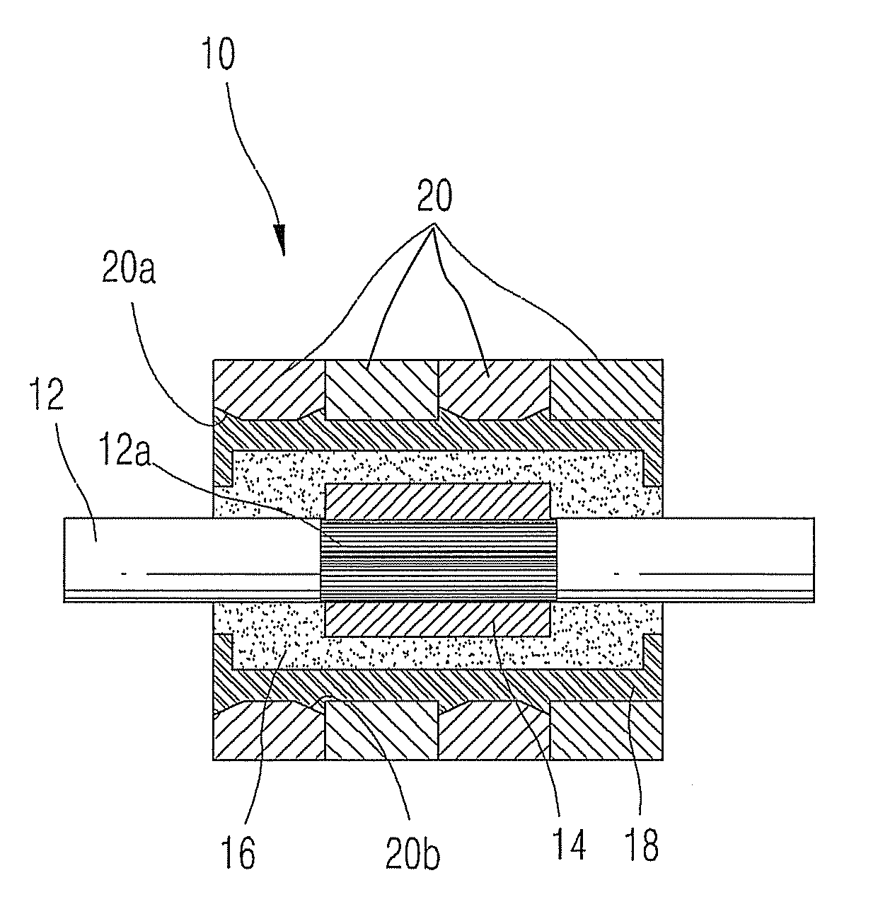
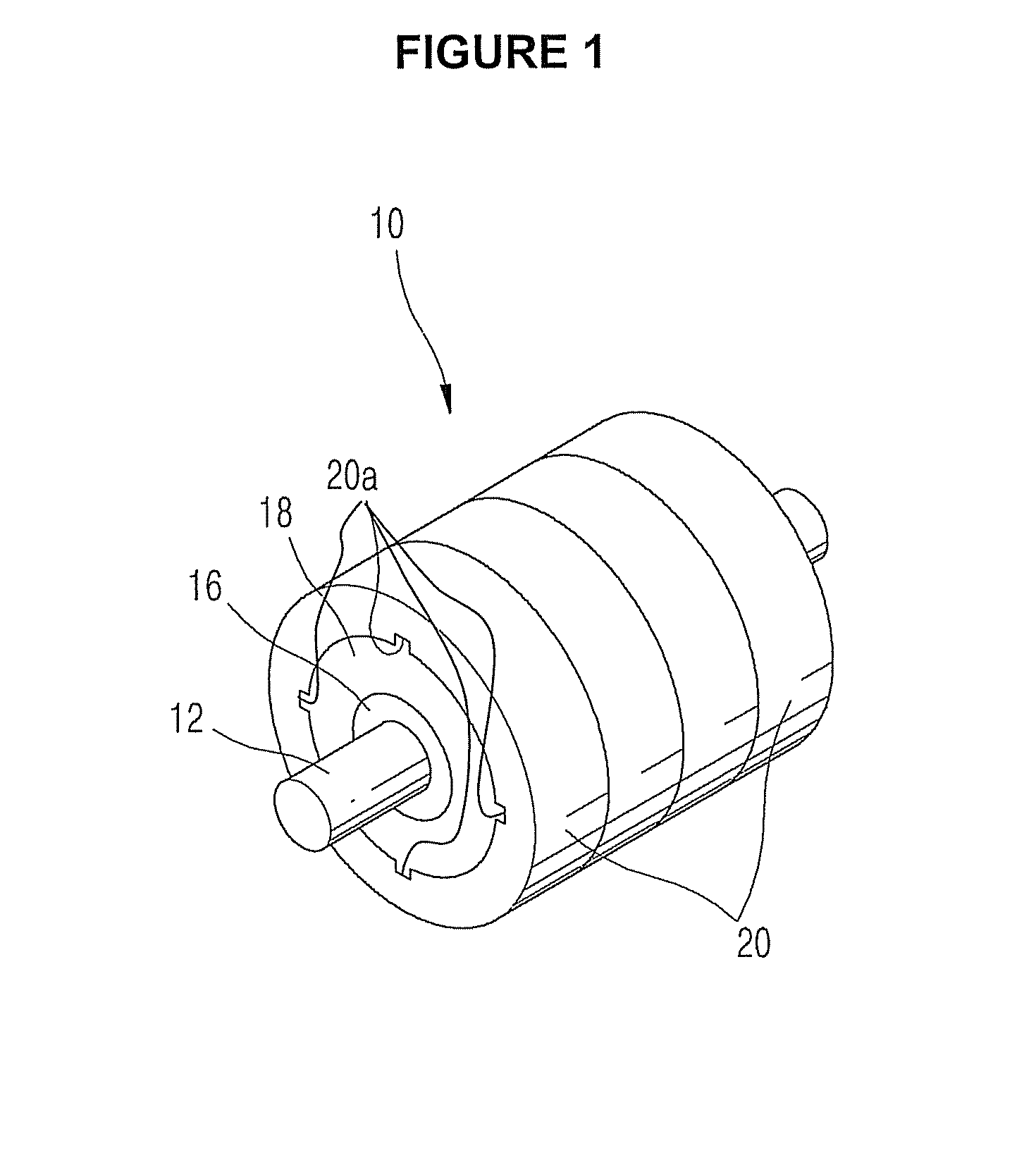
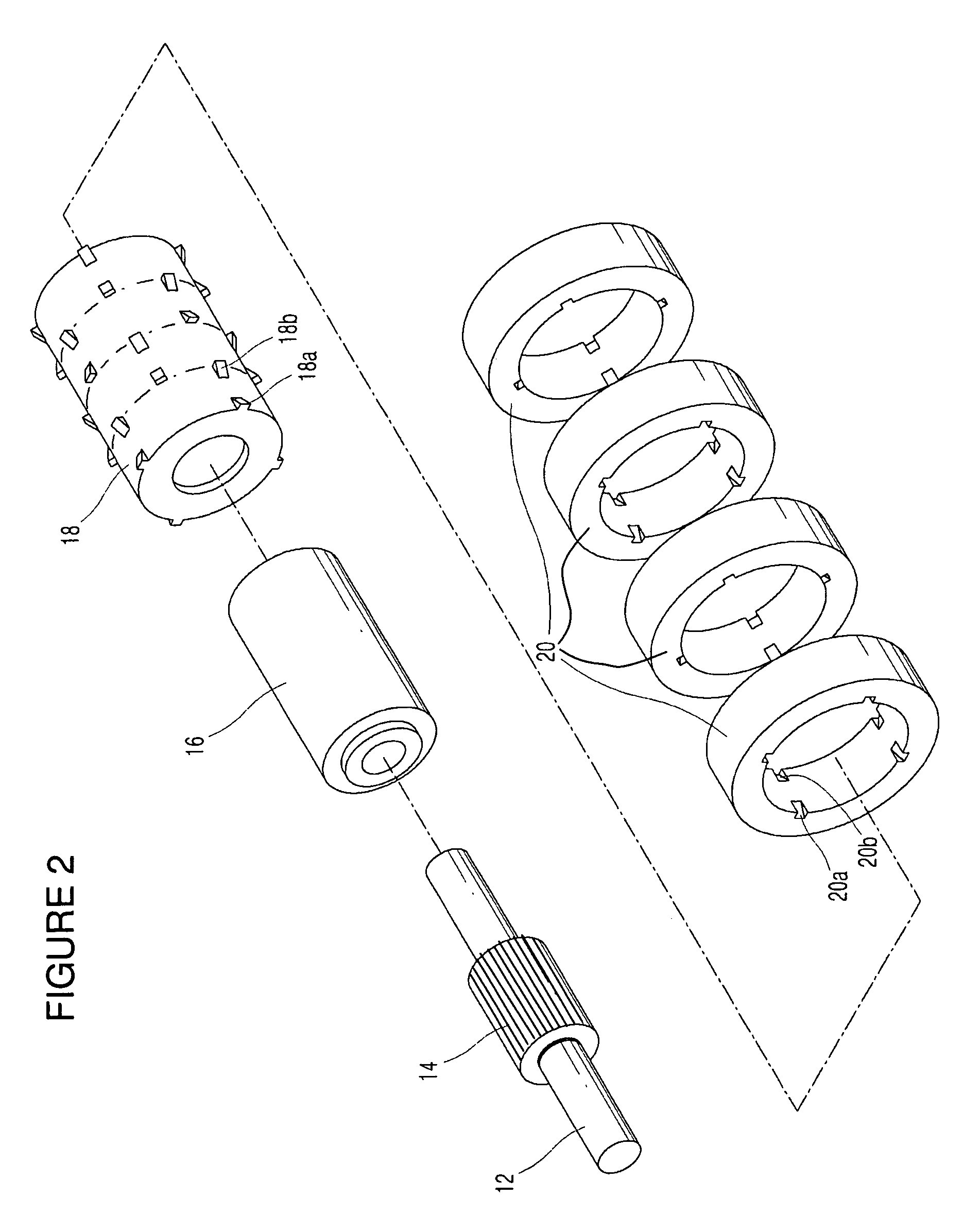
[0024]FIG. 1 is an assembled perspective view showing a rotor of a BL motor according to an embodiment, FIG. 2 is an exploded perspective view showing the rotor of a BL motor of FIG. 1, FIG. 3 is a cross-sectional view showing the rotor of a BL motor of FIG. 1, FIG. 4 is a cross-sectional view showing the rotor of a Stepping Motor, numeral number 102 denotes stator; and FIG. 5 is a cross-sectional view showing the rotor of a Micro Motor, numeral number 100 denotes stator, according to different aspects of the present invention.

[0025]A rotor of a BL motor 10 according to an aspect of the embodiment includes a rotary shaft 12, a high-strength engineering plastic 14, a sound-absorbing resin eleme...


PUM


Abstract

The present invention provides a rotor of a brushless (BL) motor, including: a high-strength engineering plastic member formed by injection-molding high-strength engineering plastic around a concavo-convex portion 12a formed on the outer circumferential surface of a rotary shaft; a sound-absorbing resin element formed by injection-molding a sound-absorbing resin around the high-strength engineering plastic member; a cylindrical ring magnet assembly including a plurality of axially aligned ring-shaped magnets, each of which has a plurality of indented grooves 20a and 20b formed on both end edges of the inner circumferential surface thereof; and a high-strength plastic member formed by injection-molding a high-strength plastic between the sound-absorbing resin element and the ring magnet assembly, the high-strength plastic member having a plurality of protrusions formed on the outer circumferential surface thereof in such a fashion that each protrusion corresponds to an associated one of the indented grooves of the ring-shaped magnets.

Description

CROSS-REFERENCE TO RELATED APPLICATIONS[0001]This application claims the benefit of Korean Patent Application No. 10-2007-0107665 filed on Oct. 25, 2007 in the Korean Intellectual Property Office, the disclosures of which are incorporated herein by reference.BACKGROUND[0002]1. Field[0003]One or more embodiments relate to a rotor of a brushless (BL) motor, and more particularly, to such a rotor of a BL motor, which minimizes the transfer of an electromagnetic vibration and a noise to a rotary shaft thereof, and enables a torque of the rotary shaft to be normally transferred to cylindrical ring magnet assembly.[0004]2. Description of the Related Art[0005]In general, a conventional rotor of a BL motor employs a permanent magnet, and is constructed such that a rotary shaft is coupled to a rotor core using a ferromagnetic material or a steel plate so as to form a magnetic circuit structure of a permanent magnet.[0006]Such a motor rotor entails a problem in that when a permanent magnet ro...

Claims


Application Information

Patent Timeline
Patent Type & Authority Patents(United States)
IPC IPC(8): H02K5/24
CPCH02K1/2733H02K1/30H02K1/28H02K1/27
Inventor JEUNG, YOUNG-CHUN
Owner BLUFFTON MOTOR WORKS
Why Eureka
Try Eureka