
Fuel system and ecology valve for use therein

a technology of ecology valves and fuel systems, applied in the field of fuel systems, can solve the problems of increasing the cost of additional components, reducing the efficiency of the system, and reducing the cost of the system

Active Publication Date: 2011-12-27
GOODRICH CONTROL SYST LTD
View PDF7 Cites 12 Cited by
  • Summary
  • Abstract
  • Description
  • Claims
  • Application Information

AI Technical Summary

Benefits of technology

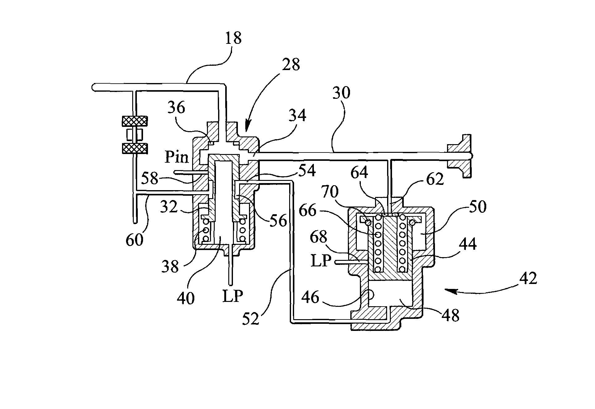
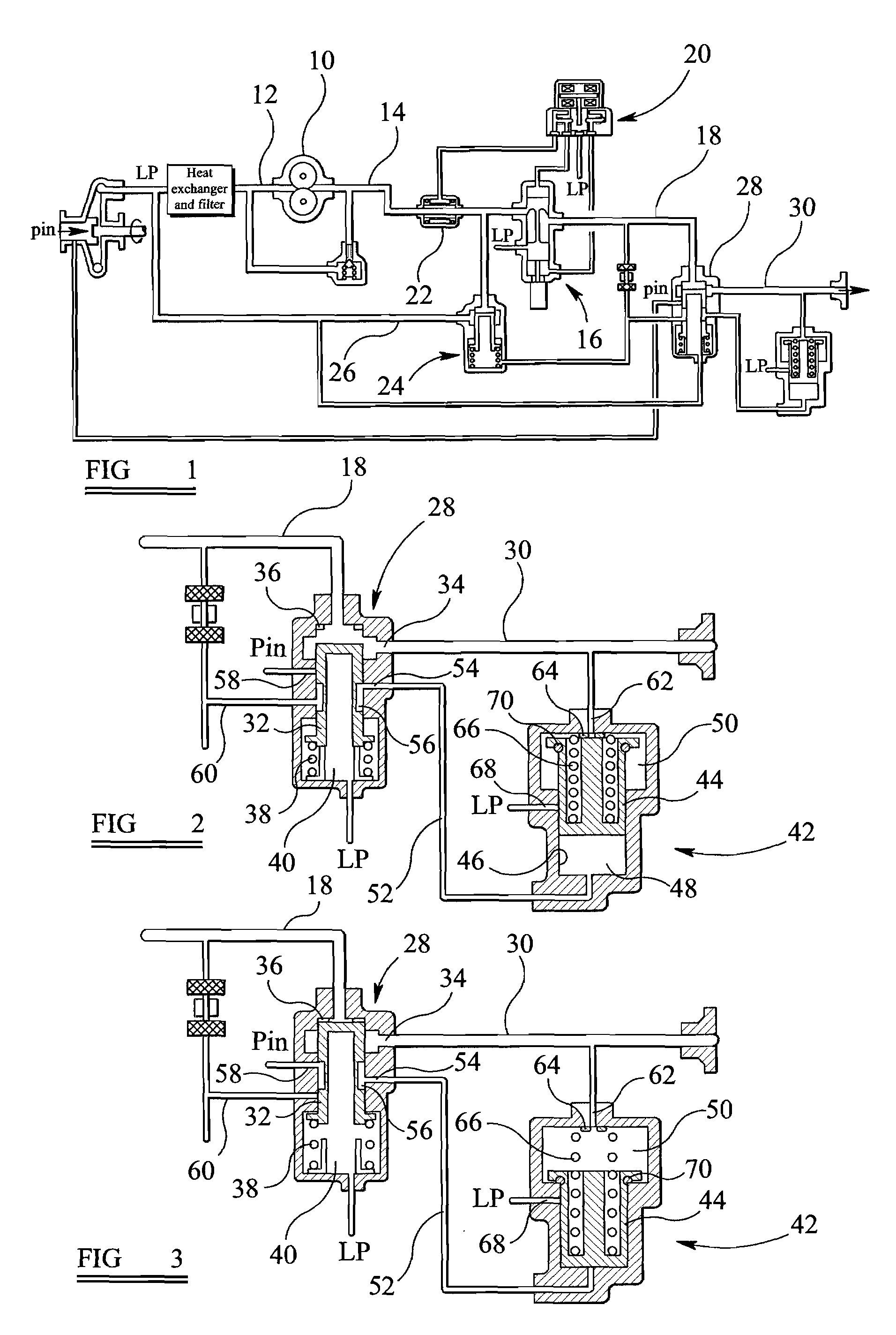
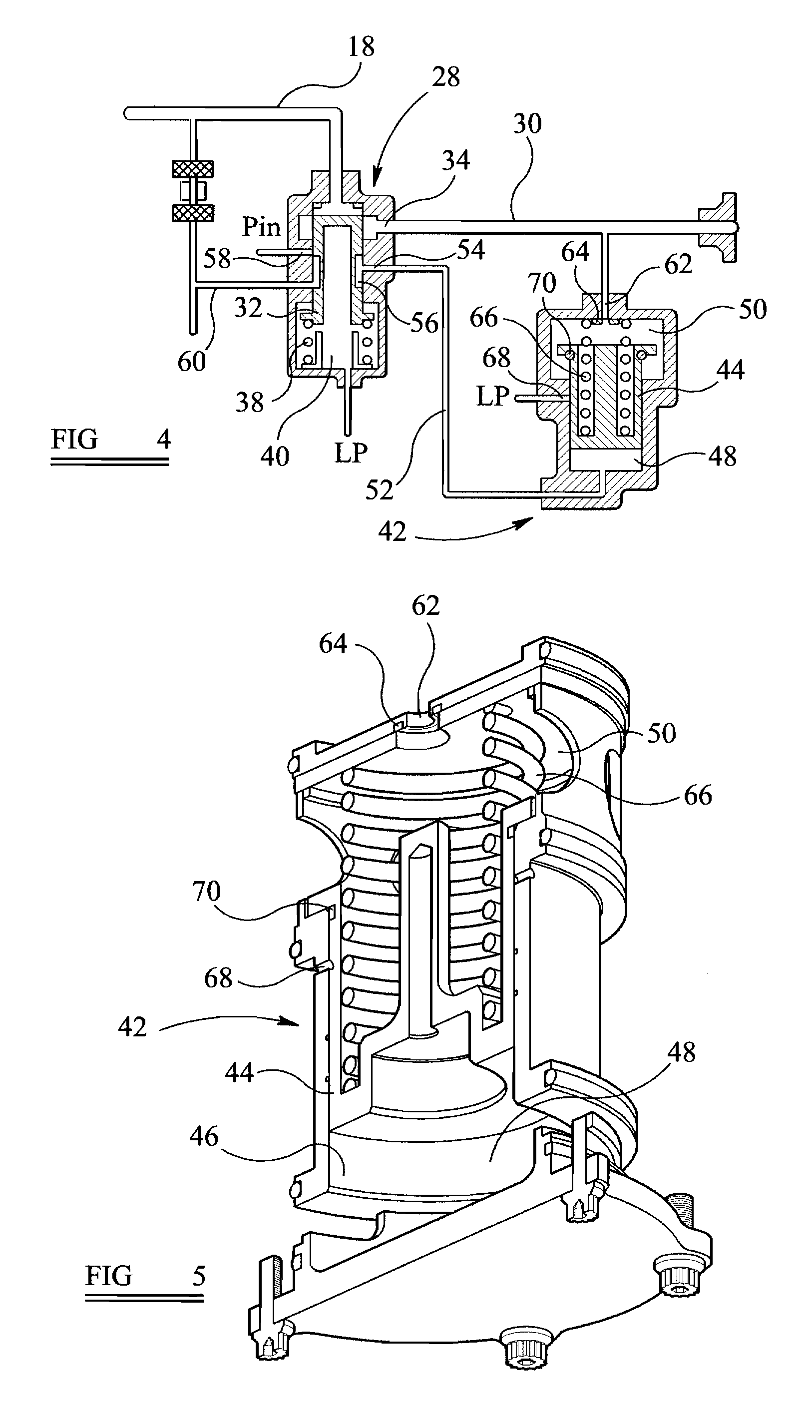
[0007]Such an arrangement is advantageous in that the control arrangement for the ecology valve is relatively simple, and the provision of the seal means results in the force acting on the piston due to the fuel pressure within the engine manifold line being relatively low.
[0010]Such an arrangement is advantageous in that, when the piston occupies its first position, the ecology chamber is at relatively low pressure thus the force urging the piston away from this position applied by the pressure of the fuel in the ecology chamber is low. When the piston occupies its second position, escape of fuel through the restricted flow path is avoided by virtue of the sealing action of the valve arrangement.

Problems solved by technology

This solution is relatively complex and costly.
To permit control over the ecology valves or pistons, relatively complex control arrangements are often required, leading to the use of additional components and this is undesirable.

Method used


Image

  • Fuel system and ecology valve for use therein
  • Fuel system and ecology valve for use therein
  • Fuel system and ecology valve for use therein

Examples


Embodiment Construction

[0018]The fuel system illustrated diagrammatically in the accompanying drawings comprises a high pressure gear pump 10 arranged to pump fuel from an inlet line 12 in which the fuel is at relatively low pressure to a supply line 14. A metering valve 16 receives fuel from the supply line 14 and controls the delivery of fuel from the supply line 14 to a delivery line 18. The metering valve 16 is controlled by a servo arrangement 20 which is supplied with fuel under pressure from the supply line 14 via a flow washed filter 22. The operation of the metering valve 16 is conventional and will not be described in further detail.

[0019]A spill valve 24 is provided and is operable to maintain a substantially constant pressure drop across the metering valve 16. In the event that the pressure drop across the metering valve 16 exceeds a pre-determined level, then the spill valve 24 will open to allow fuel to be diverted from the supply line 14 to a spill line 26.

[0020]A pressurising valve in the ...


PUM


Abstract

A fuel system comprises a pressure raising valve operable to control communication between a fuel delivery line and an engine manifold line, and an ecology valve comprising a piston movable within a bore, the piston and bore together defining a control chamber and an ecology chamber, the ecology chamber communicating with the engine manifold line, the pressure within the control chamber being controllable to control the position occupied by the piston, the ecology valve further comprising seal means whereby, when the piston occupies a first position in which it engages the seal means, only a first, relatively small, effective area of the piston is exposed to a fuel pressure within the engine manifold line, a second, larger, effective area being exposed to the fuel pressure within the engine manifold line when the piston occupies a position in which it does not engage the seal. An ecology valve for use in the fuel system is also described.

Description

BACKGROUND OF THE INVENTION[0001]This invention relates to a fuel system, and in particular to a fuel system intended for use in aerospace applications and of the type including an ecology function. It also relates to an ecology valve to provide the ecology function.[0002]It is desirable to provide fuel systems with an ecology function so that, upon or after engine shutdown, a quantity of fuel can be removed from the engine fuel manifolds. Such removal is advantageous in that fuel evaporation into the atmosphere is reduced and coking of the engine fuel nozzles is also reduced. There are thus environmental and engine performance and reliability benefits to the provision of an ecology function.[0003]One known ecology function is provided by using a dump valve, operable when the engine is shut down, to allow fuel to flow from the manifold to a drains tank, and using a pump to return the fuel from the drains tank back to a fuel reservoir or to the input to the fuel system during a subse...

Claims


Application Information

Patent Timeline
IPC IPC(8): F16K31/12
CPCF01D25/32F02C7/232F02C9/26F05D2260/602
Inventor MAKER, PAUL MANWARING
Owner GOODRICH CONTROL SYST LTD
Learn More